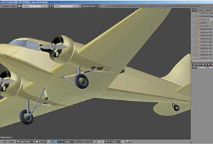
Let’s continue modeling the plane nose. Last time I made the cockpit glazing. Now we need to make the nose of the fuselage.
Let’s see what we have.
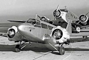
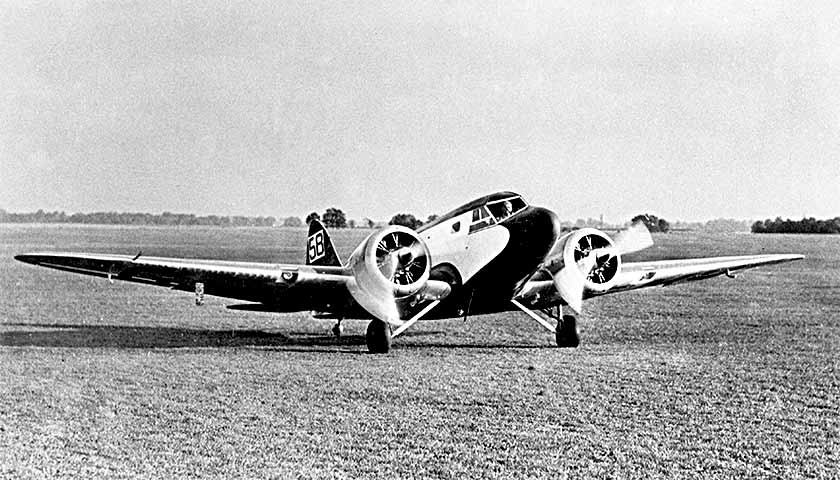
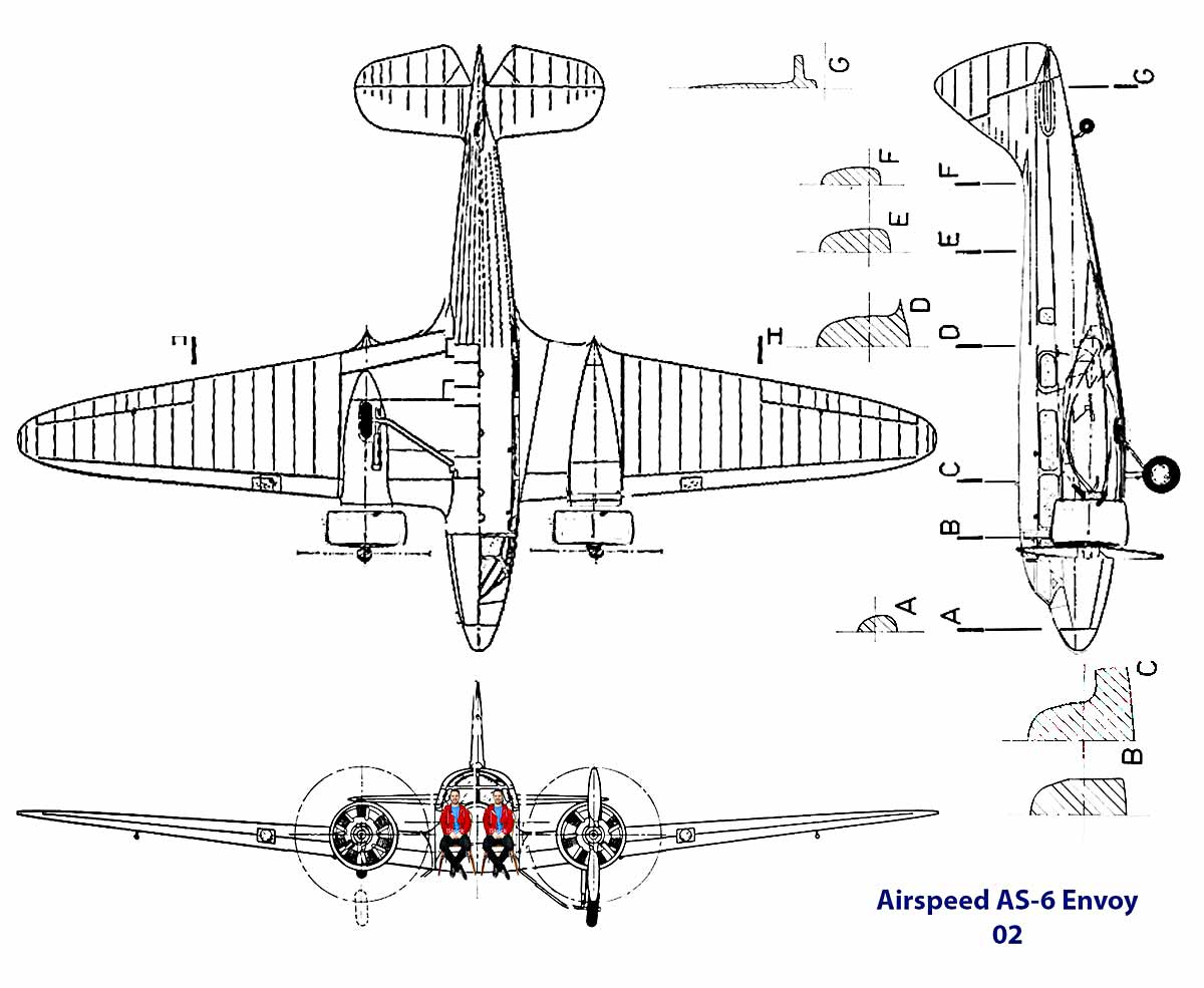
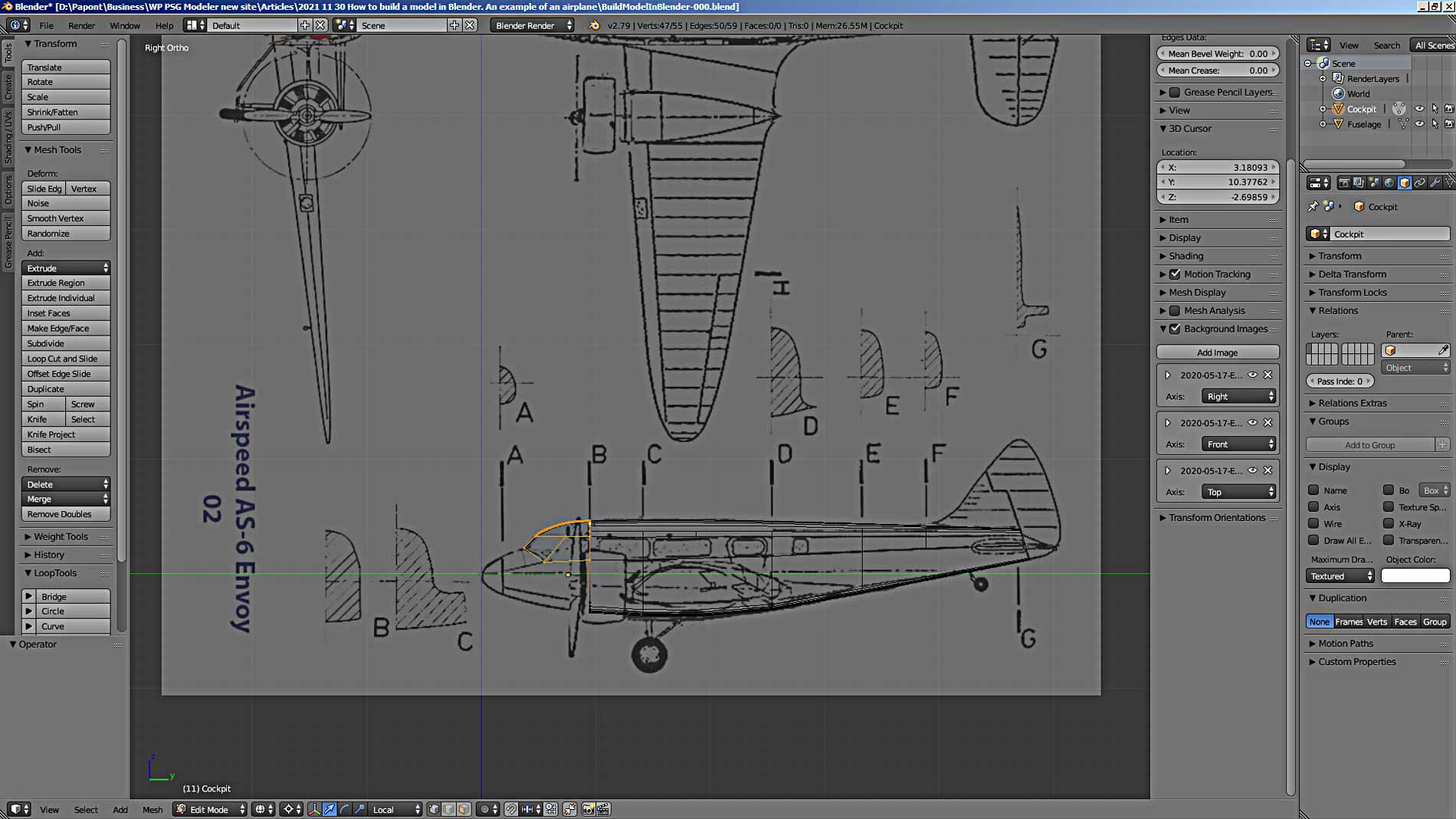
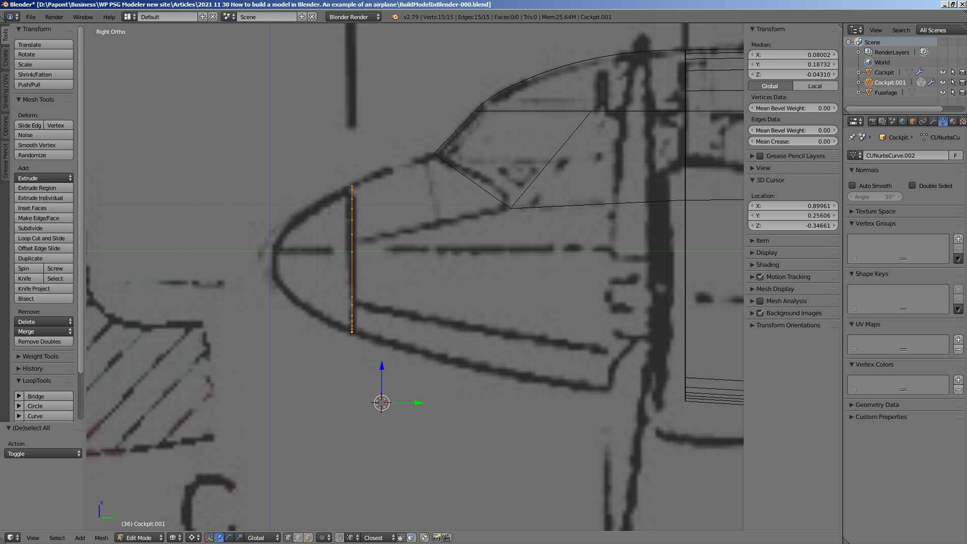
The picture “Right View” shows that we have only the contour of the nose and section A along the nose of the fuselage. In this case, we see that the side of the fuselage is flat and vertical. The photographs additionally show that the plane nose has an elliptical cross-section, smoothly turning into a flat side.
Here I will make a small digression back to my story. When I made the main part of the fuselage, I used only two sections, B and C. I did this to simplify my story so as not to overload it with information.
Now it’s time to notice that the entire fuselage had to be coordinated with the sections C, D, E, F and G available in our picture. But, I think, after the completed construction of the fuselage, you will be able to coordinate the shape of the fuselage with the existing sections yourself. Let this be your task. I will post the solution a little later and talk about the modeling techniques that I used in doing this work to make the geometry of the model as accurate as possible.
So, section A. Copy section A from the original picture and place it on our drawing, where the plane is presented in three views. We agree on the cross-section for the size of the fuselage in this place. This procedure must be done for each fuselage slice. Here is an example of substitution on the drawing of section E from the original picture.
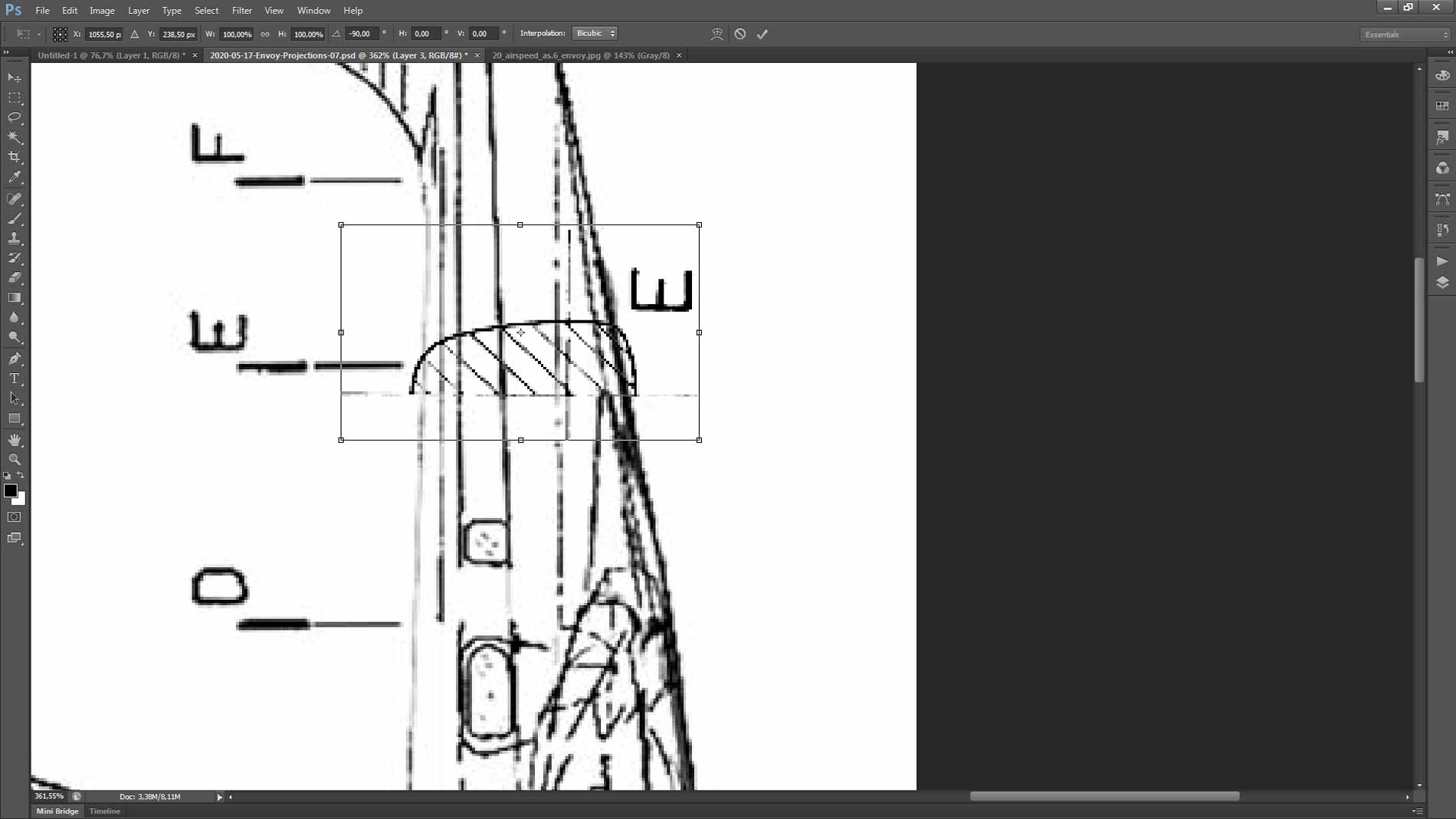
It can be seen that the section must be reduced in height and, accordingly, in width. So that the decrease is proportional. It’s easy to do this in Photoshop. It is necessary to change the size by pressing the Shift key. Here’s what you should get.
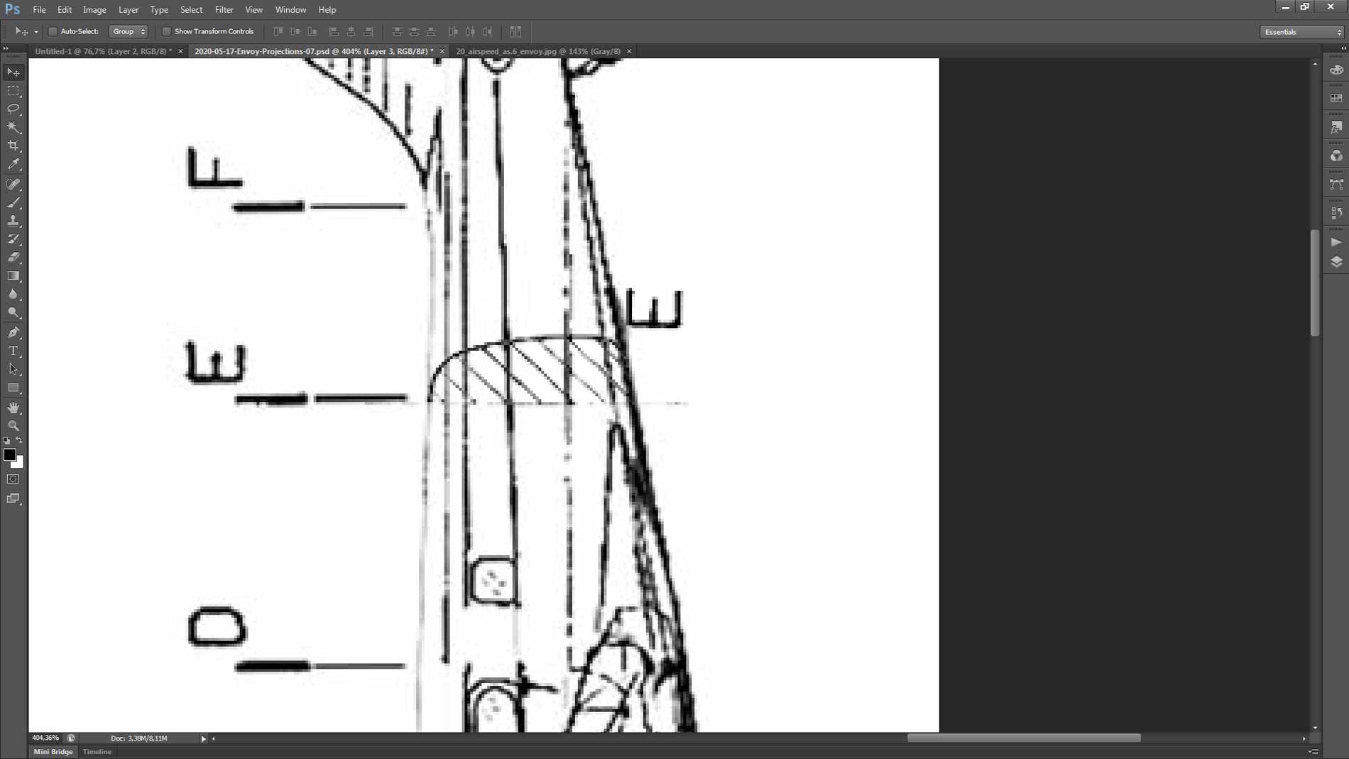
Here is our updated drawing with all cross-sections.
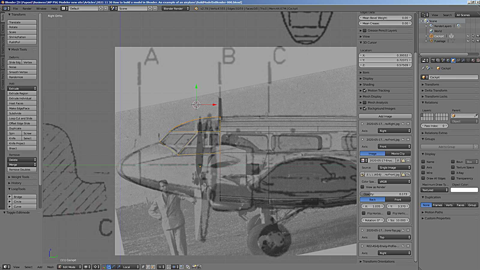
Substitute the drawing into the main Blender window.
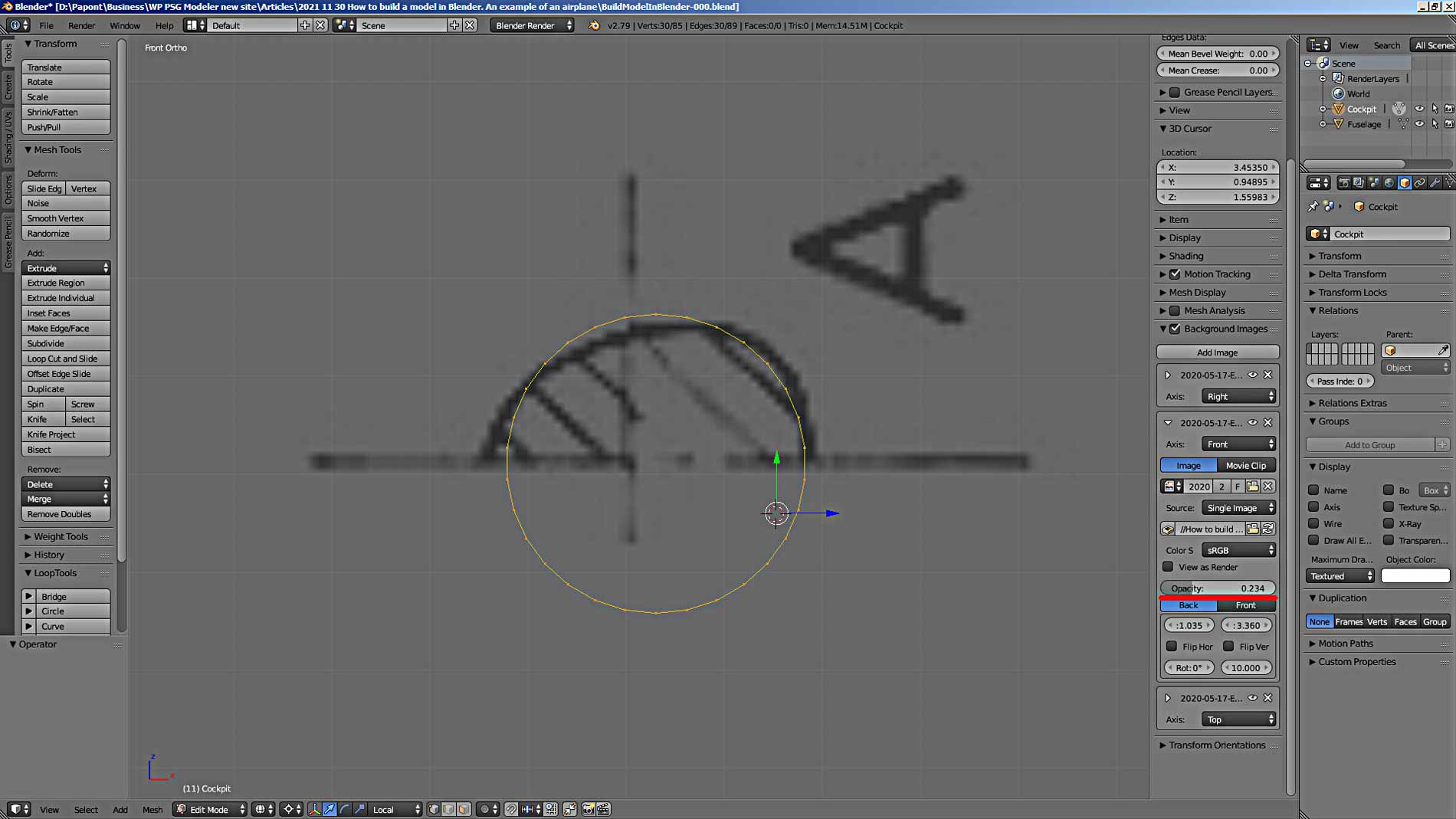
Let’s put section A of the fuselage in our model. To do this, first you need to model section A. Let us remember how many vertices there are in section B. In section A, you need to make the same amount to make it easier to dock the parts of the fuselage. So, section B consists of 15 vertices.
Add a 30-point circle to the main Blender window. Then we remove half and get half of section A, consisting of 15 vertices.
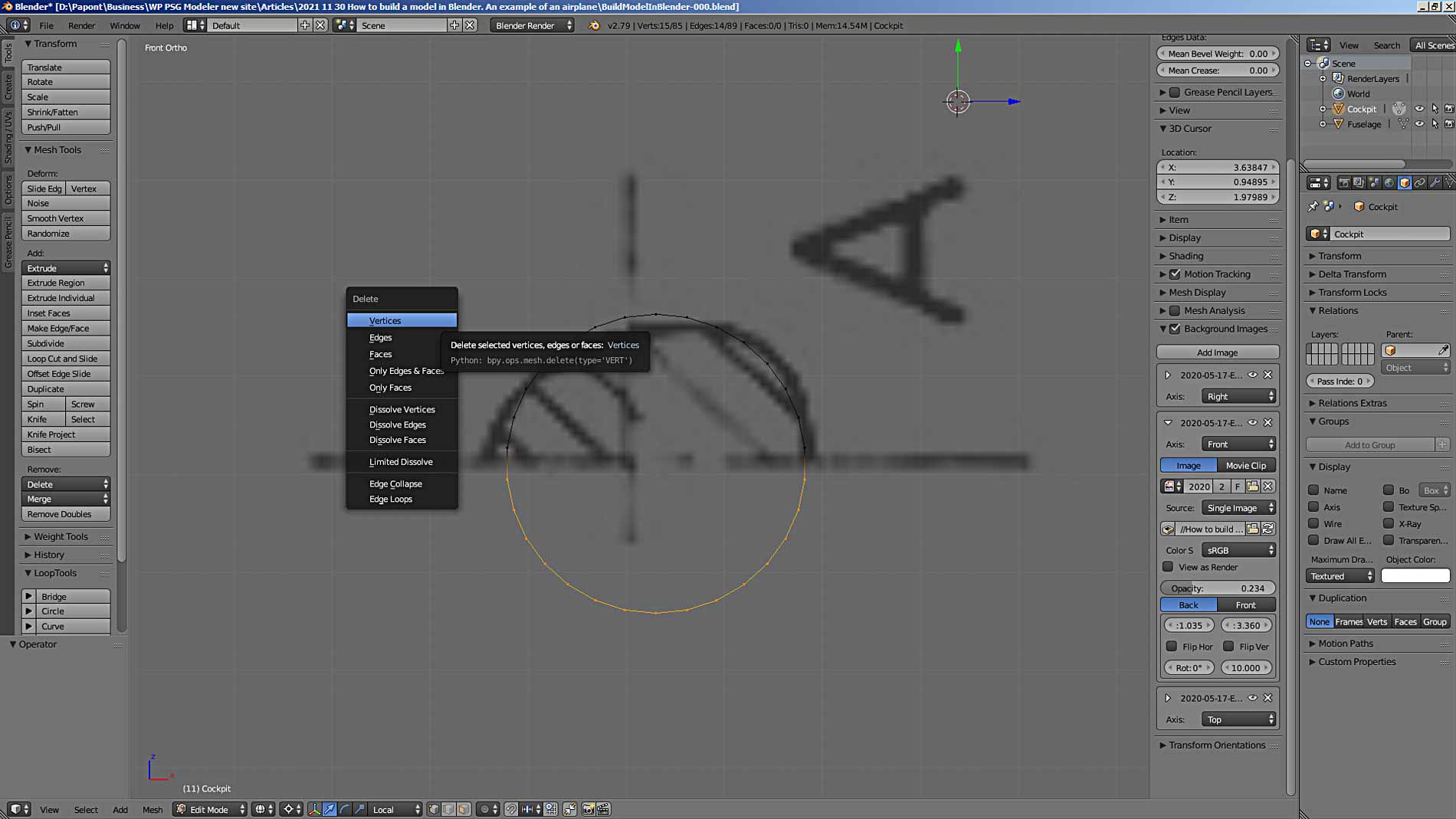
I placed the vertices manually. It turned out badly, since my original picture is bad. To improve the result, you must first make the contour of section A using a curve. Then convert it to a mesh and reduce the number of vertices to 15.
You can convert the curve to a mesh and make it a separate part. Then it will be possible to superimpose the vertices of the already obtained section on the mesh obtained from the curve, as on a template. Let’s do it.
If the available control points in the NURBS curve are not enough to build the desired shape, then you can add the necessary points with the Subdivide command in the same way as we add the necessary vertices to the mesh.
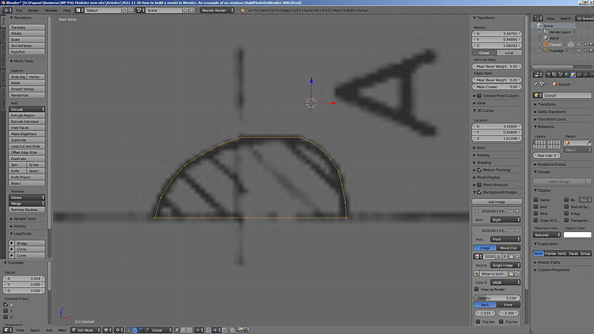
As a result, a shape is obtained that is close to the shape of section A.
Switch to Object Mode and convert the curve to mesh using the Alt + C command. Make sure that both the curve and the mesh of Section A lie in the same plane, so that the vertices do not “scatter” in the modeling space.
Now, the vertices of the contour of our section A can be easily placed on the mesh that we got from the curve. To do this, use the Snap command. It is activated by the button located on the bottom button bar of the main Blender window and provides a choice of five options. We are using the vertices “glue” option. See the rest for yourself. There is a lot of useful information there.
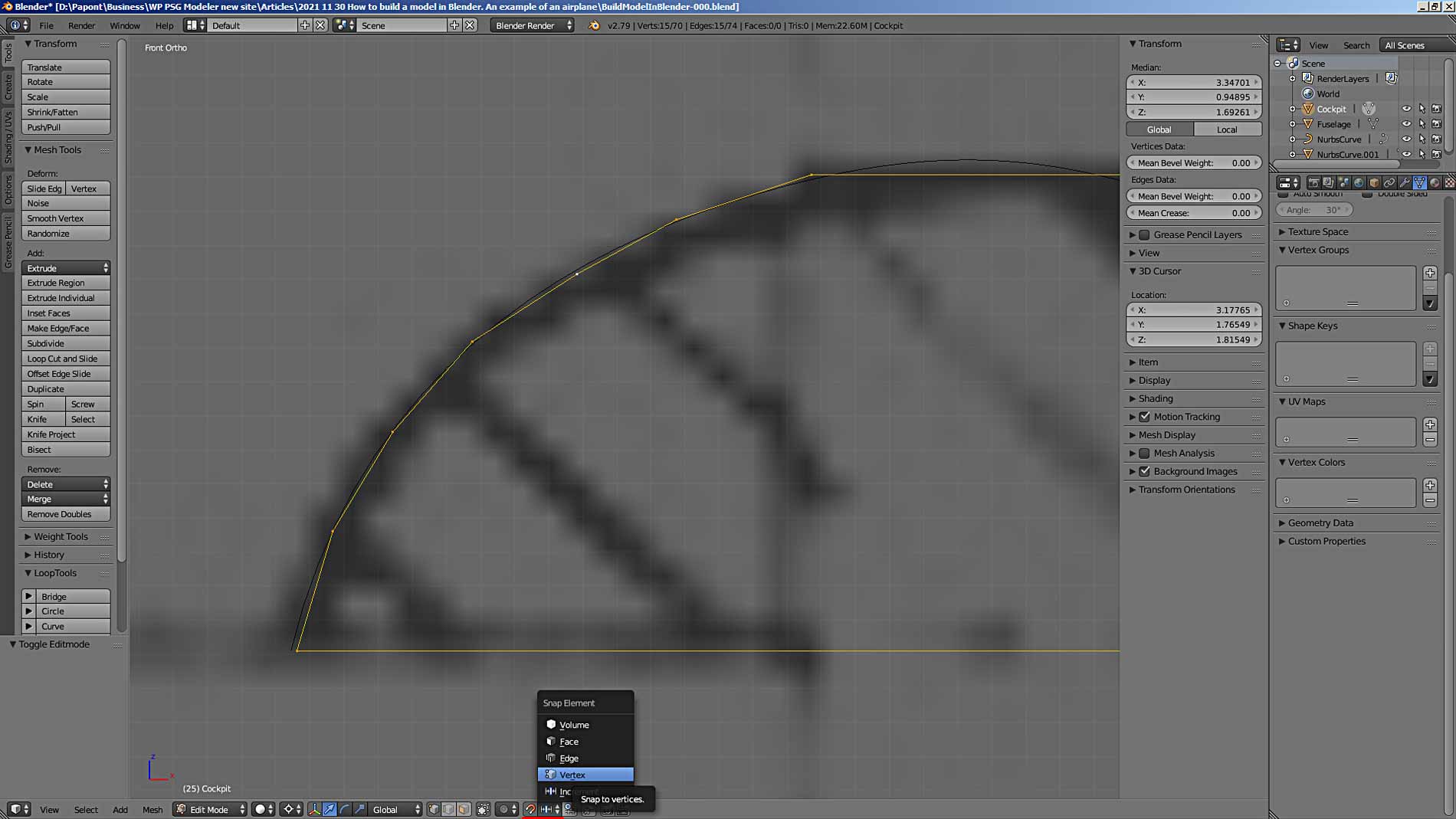
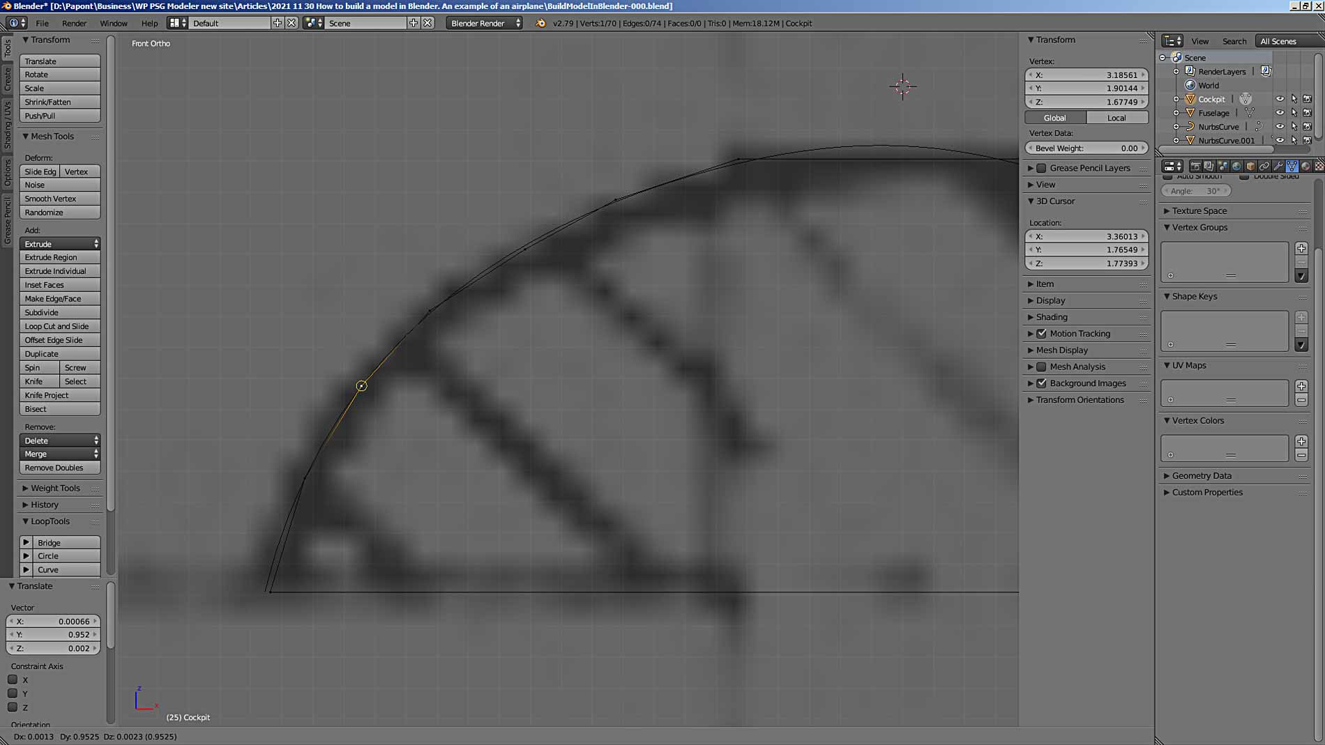
Now, when you move the vertices, they will “stick” to the vertices of the mesh that we got from the curve. When this happens, the vertex is highlighted with an orange circle.
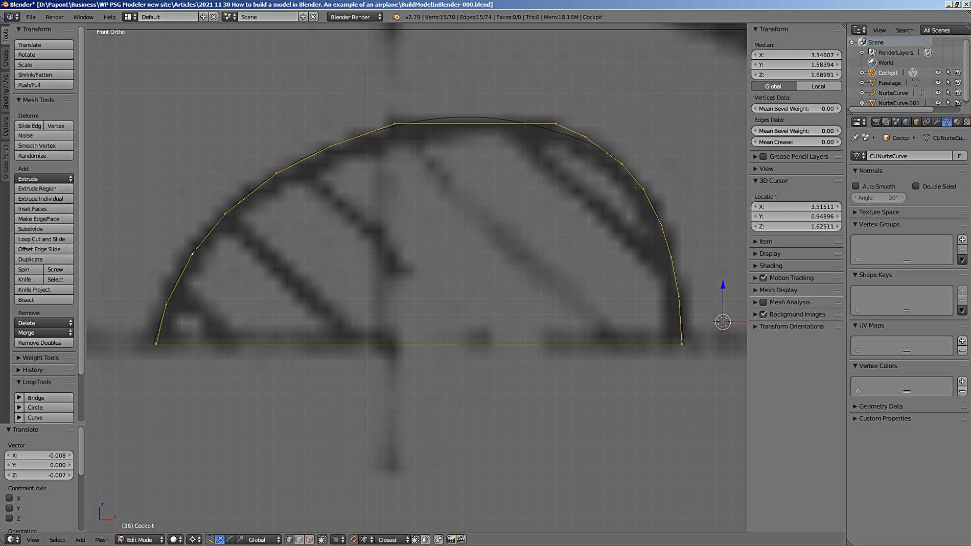
Now we have got a more “beautiful” shape of section A. You should not be confused that the shape has turned out to be noticeably “faceted”. The absolute height of this part is 13 mm.
Otherwise, if the part was much larger, then the number of vertices would have to be increased in order to represent this part in a smoother form. This scale effect must be taken into account when designing the model. If your computer has a powerful processor and a powerful video card, then you can constantly work with a big number of vertices.
However, this would be redundant information about the model. You should always adhere to an approach to designing a 3D model based on the principle of reasonable sufficiency.
Now we put the resulting section A in its place in the fuselage.
When moving section A, use the technique of substituting the coordinates of the vertices you need into the corresponding coordinates of the 3D cursor. In this way, precise positioning of parts is possible. To put section A exactly on the coordinate axis, I brought the 3D cursor to the lower point of the diametrical plane of section A. Then I went into Object Mode and executed the command Object – Transform – Origin to 3D cursor. As a result of the command execution, the Origin point of section A moved to the diametrical plane of section A. By setting the x = 0 coordinate for the section, I moved it exactly on the Z axis.
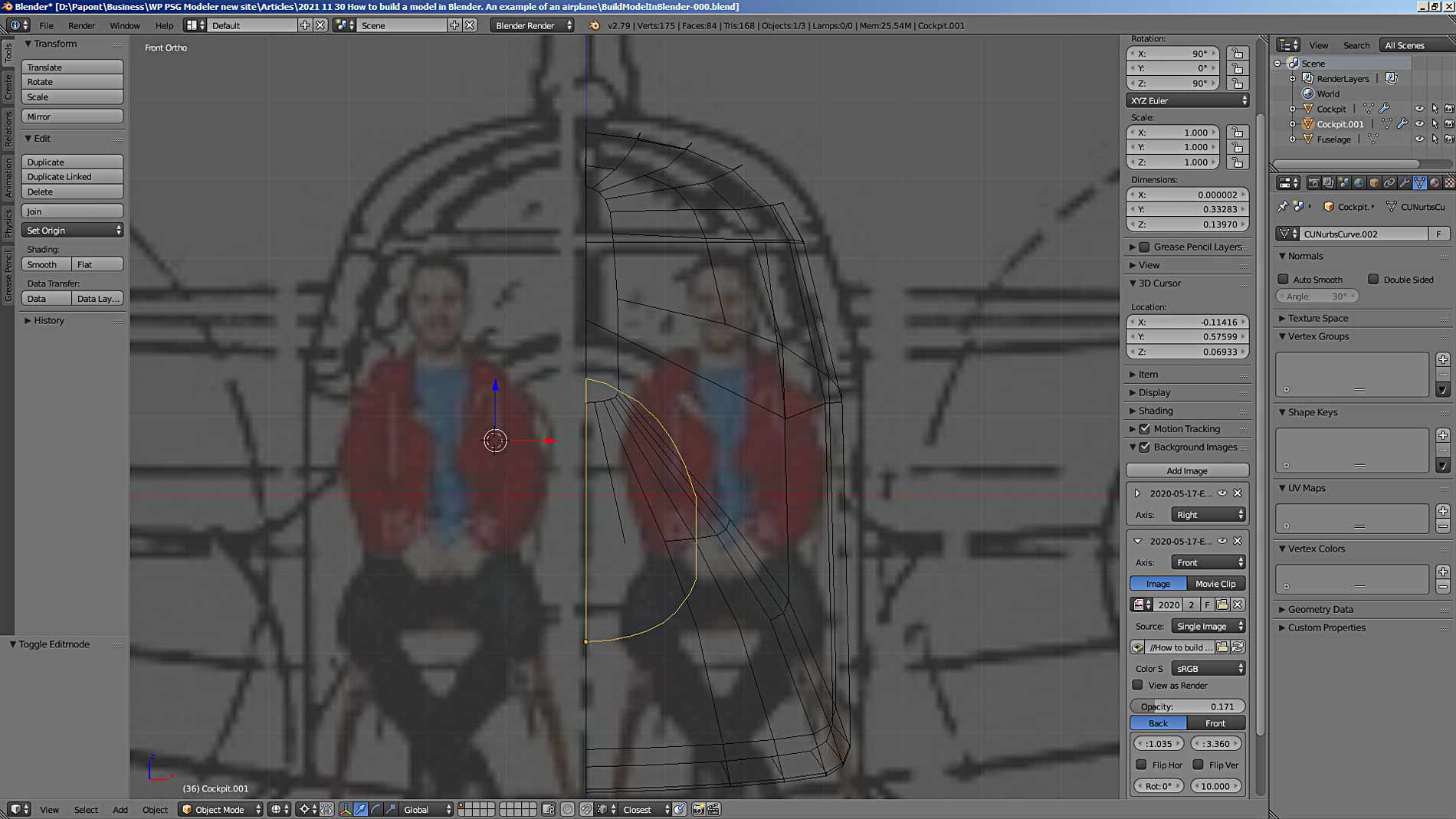
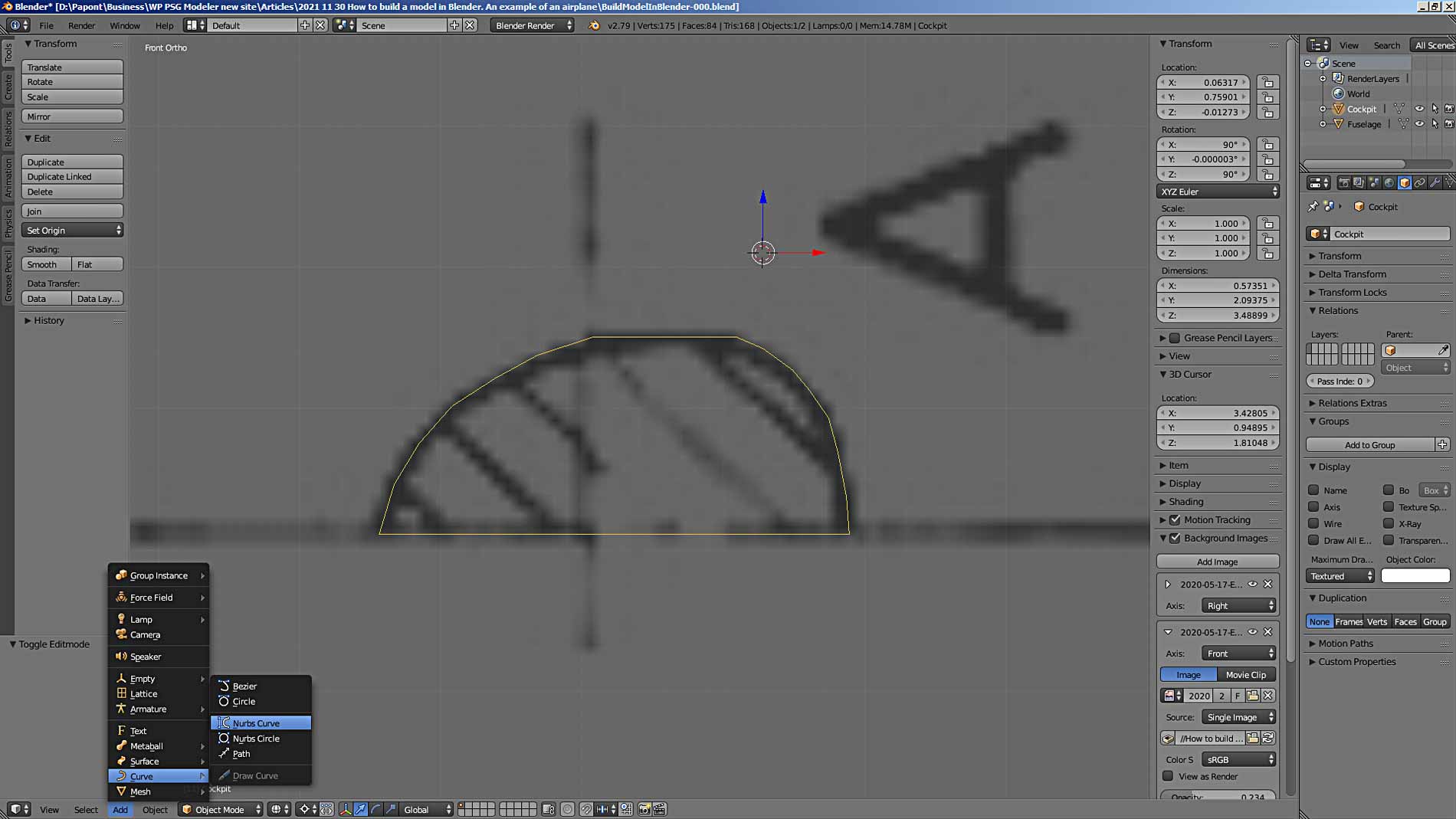
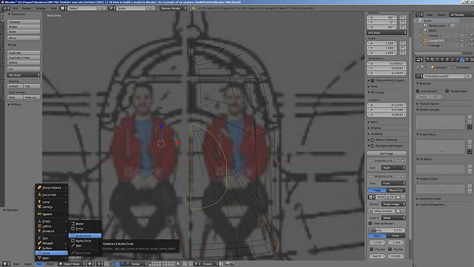
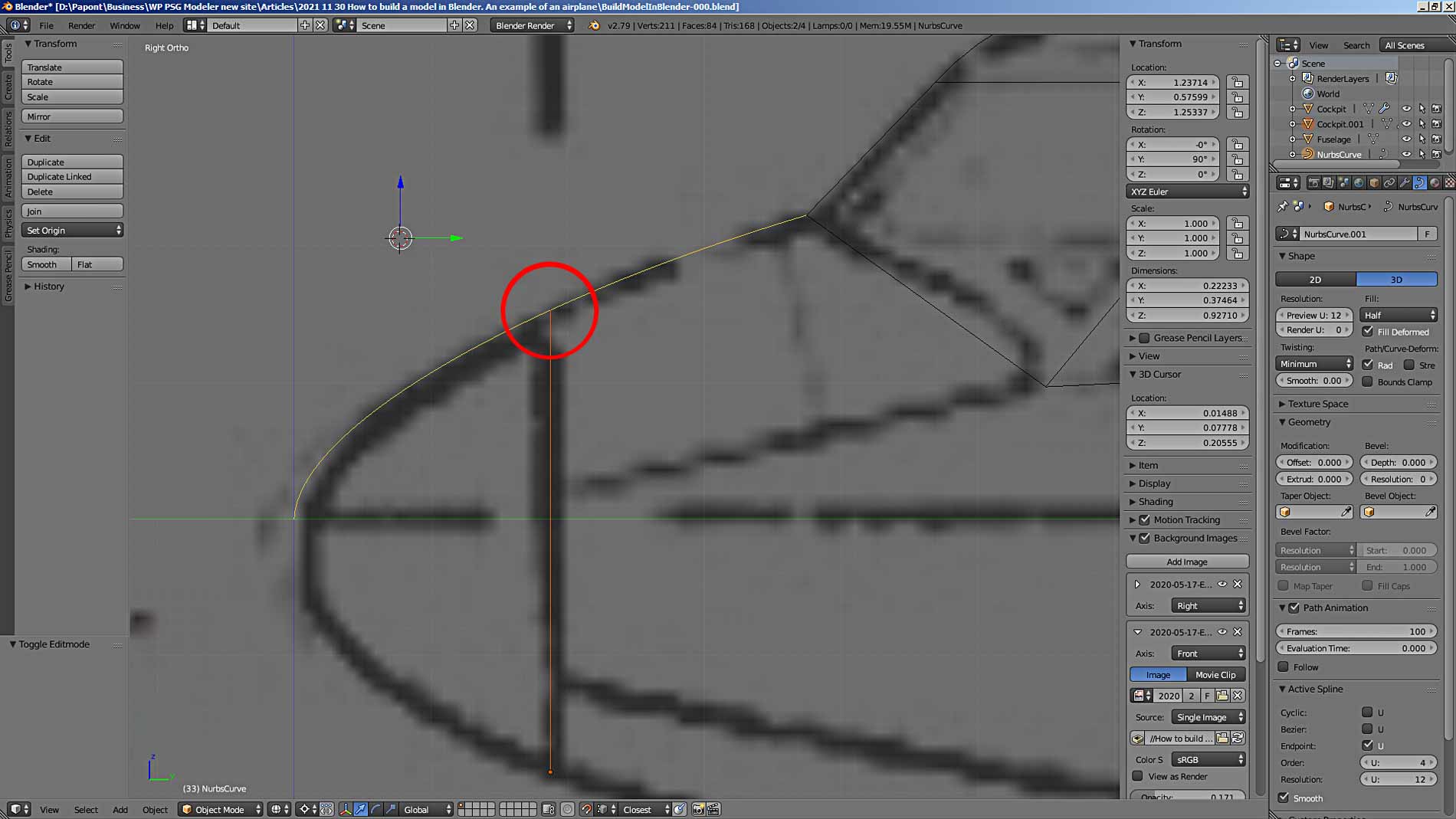
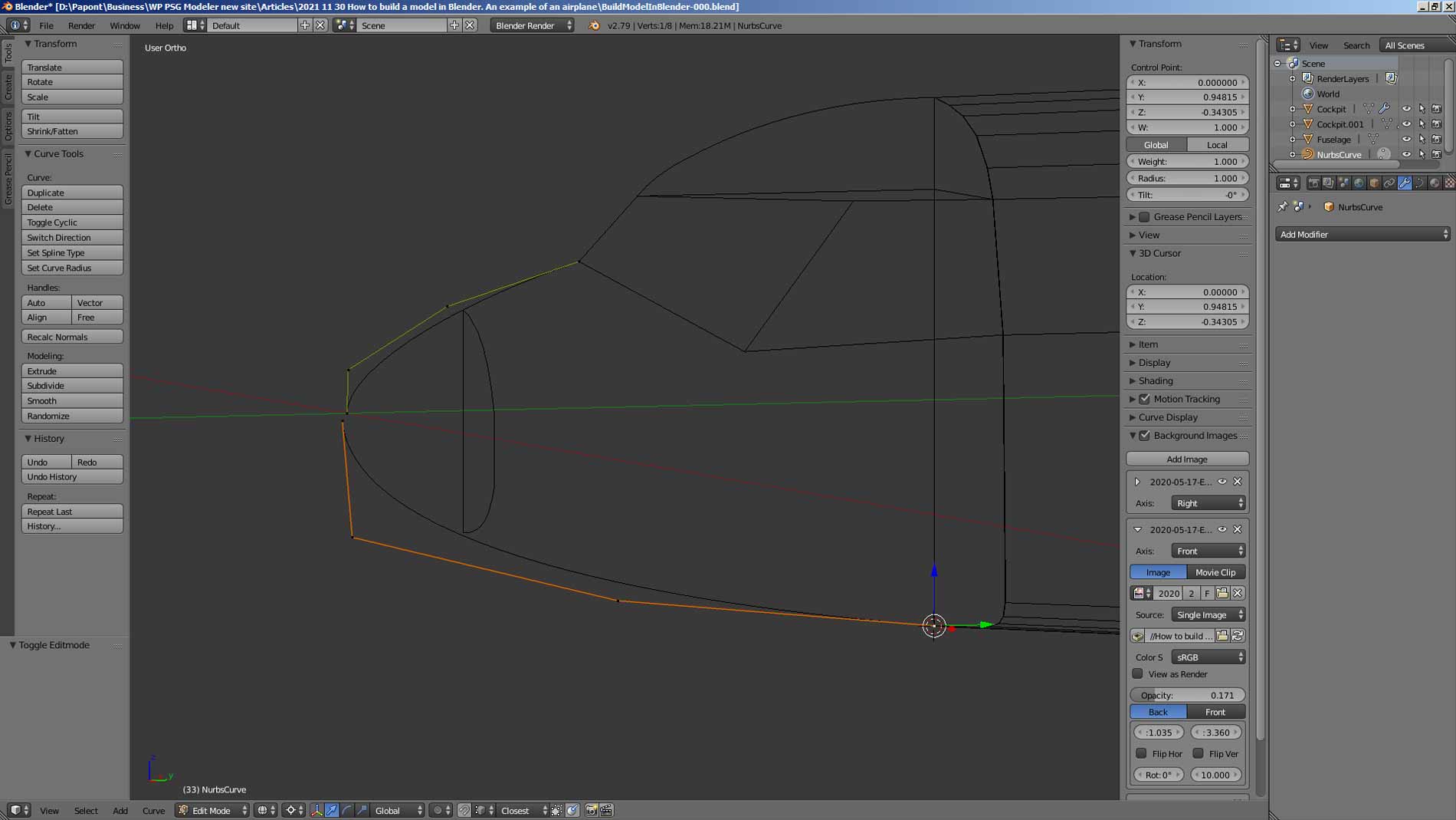
Now we need to draw the contour of the nose of the fuselage. This is most easily done using the NURBS curve. Add it to the main Blender window, Add – Curve – Nurbs Curve.
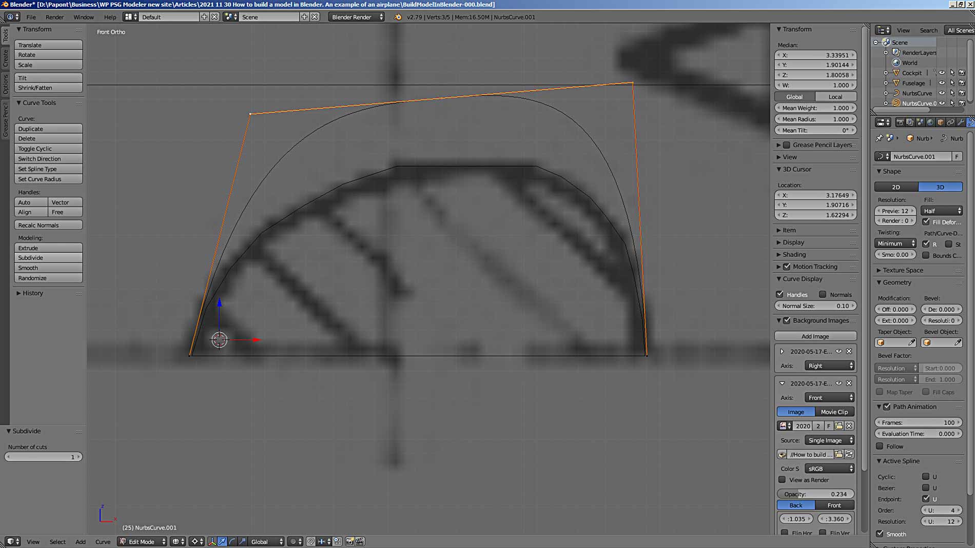
After “taming” the curve, adding end segments to it and “shaving its hair” it, we get the following picture.
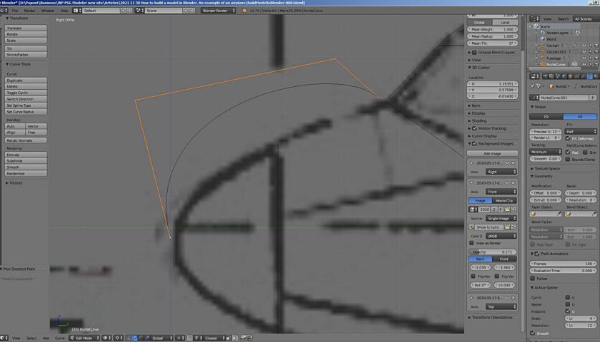
Note that the endpoints of the curve are well-defined. Their coordinates along the X axis are equal to 0. The points lie in the diametral plane. Moreover, the right extreme end of this curve should coincide with the front lower vertex of the front glass of the cockpit. This is easy to do if you turn on the Snap – Vertex command again and “glue” it to the “cockpit glass”.
The leftmost end of the curve should have a z = 0 coordinate, since I will put it at the origin. The rest of the points have only the coordinate x = 0, because the fuselage contour line lies in the diametrical plane of the plane fuselage.
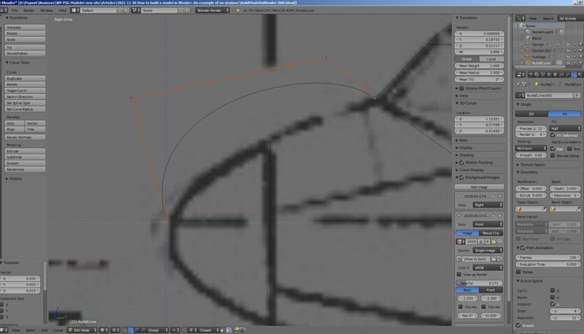
Align the curve with the outline in our drawing. Do not forget that it must pass through the upper point of section A, which lies in the center plane of the aircraft. All points of the curve must lie in the diametral plane, that is, have the coordinate x = 0.
Now you can copy the resulting curve with the Shift-D command and get a blank for the lower part of the contour. Copying with this command is possible in the Edit Mode.
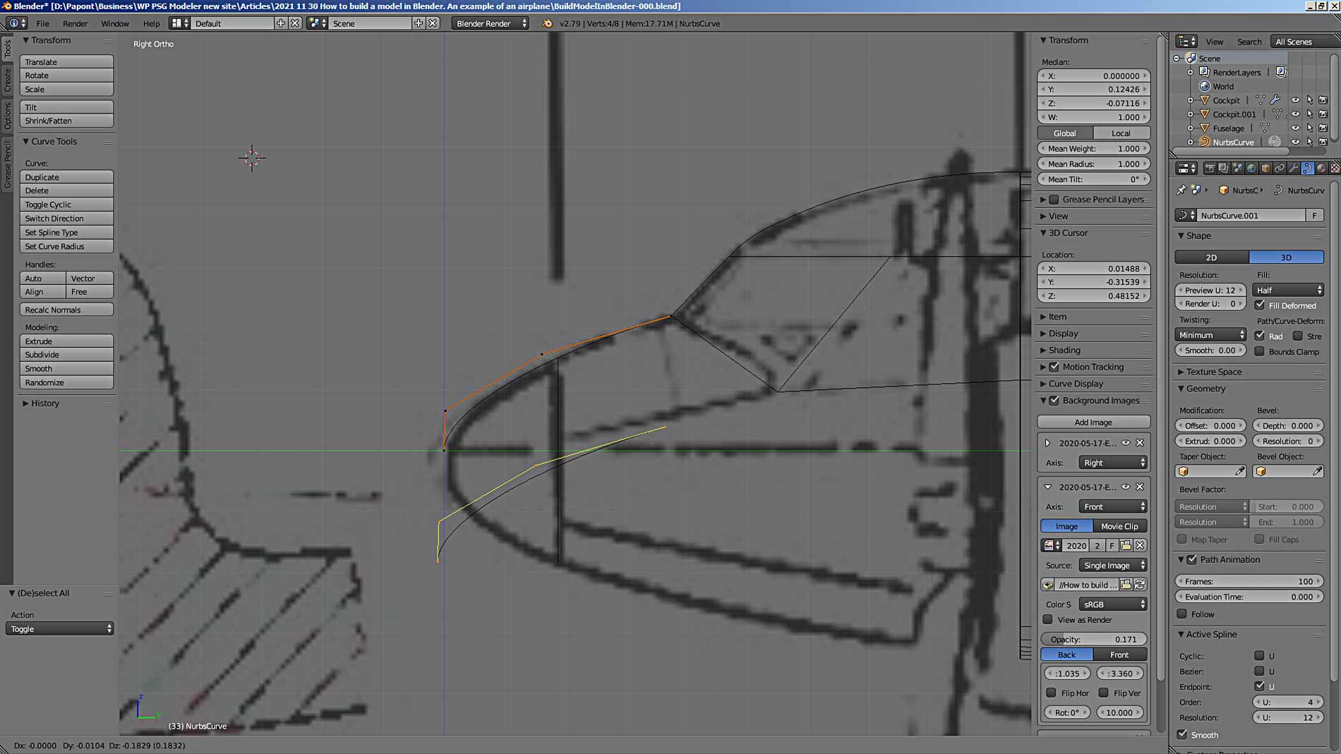
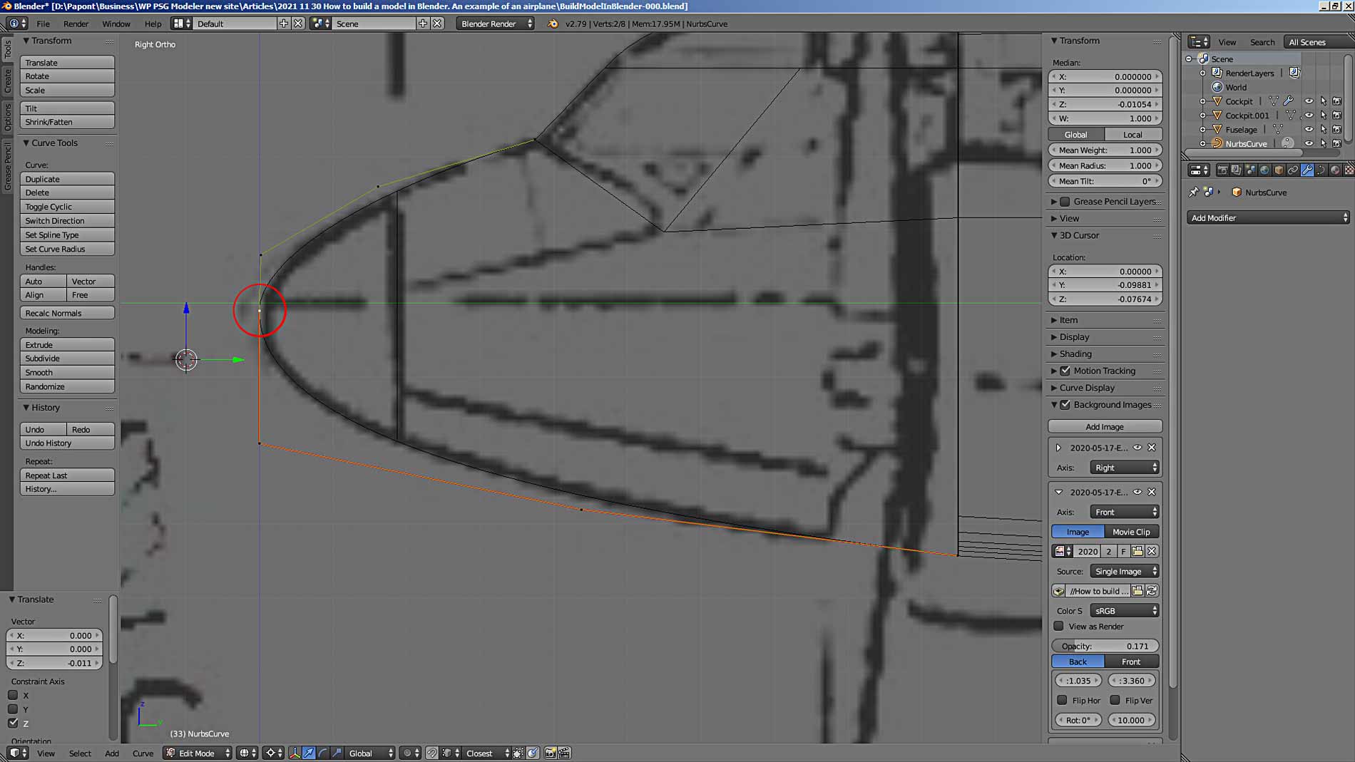
The situation repeats itself. We know the exact coordinates of the end points of the curve. All the vertices of the curve must lie in the diametral plane, that is, have the coordinate x = 0. Let’s put the vertices in the places we need. For this, use the values of the coordinates of those vertices where the vertices of our curve should stand.
To do this, I put the cursor at the lower point of section B, which we require, lying in the center plane of the plane. I put the coordinates of this vertex in the coordinates of the 3D cursor.
Now let’s move on to editing the lower curve of the nose of the fuselage contour. The 3D cursor must remain in place.
I now substitute the coordinates of the 3D cursor in the coordinates of the right end vertex of the bottom curve. She takes the position I need.
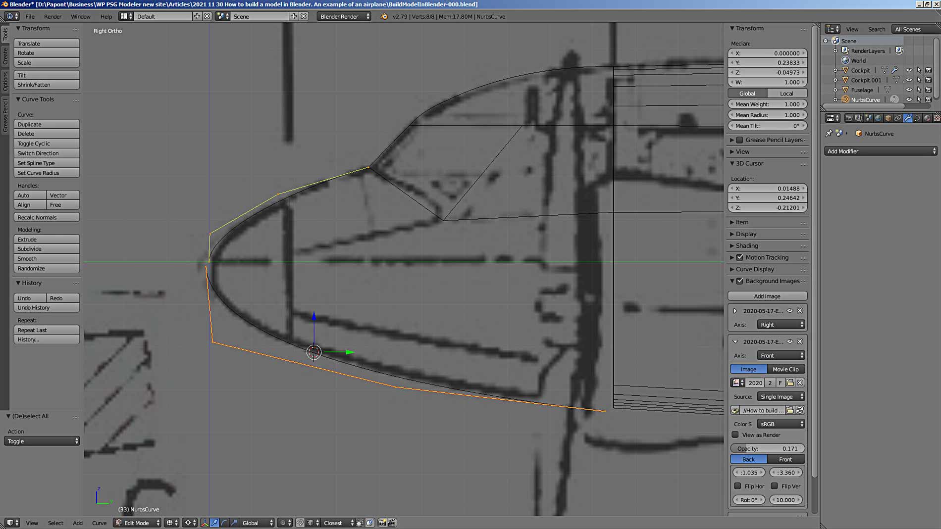
I perform similar actions with the rest of the curve vertices. Also, make sure that the curve passes through the lower diametrical point of section A. As a result, I got the contour of the plane’s nose, consisting of two curves.
With the Separate (P) command in Edit Mode, you can separate the selected vertices from the overall structure. Conversely, using the Join command (Ctrl + J) in Object Mode, you can combine parts into one assembly.
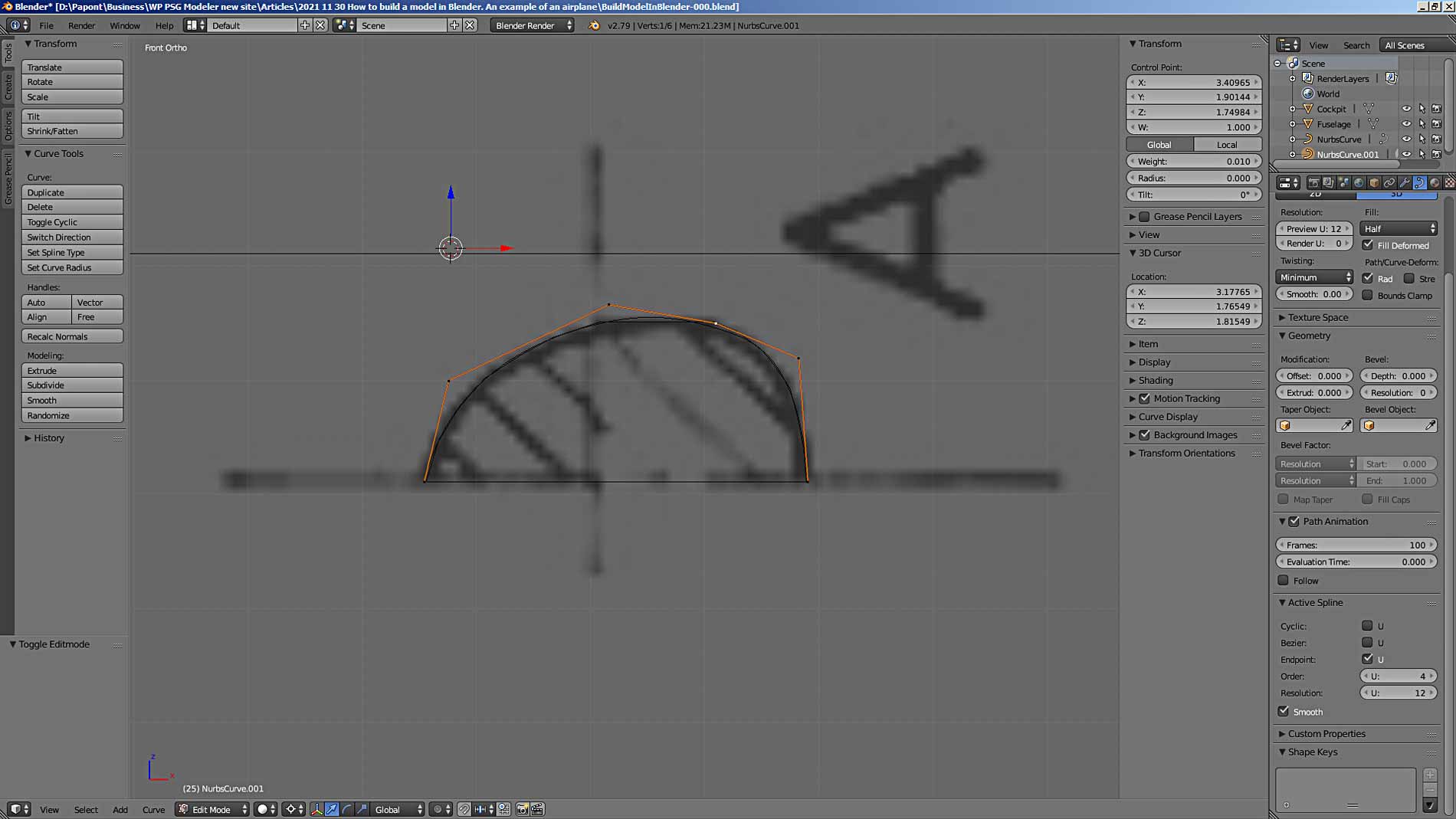
I didn’t really like how the very nose vertex of the contour looks, and I lowered it down a little. Got better.
Now we need to transform the contour into a mesh and combine it with the mesh of section A. Then I can refine the vertices at which the contour intersects with section A.
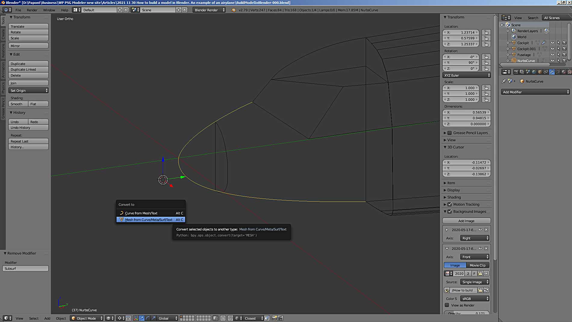
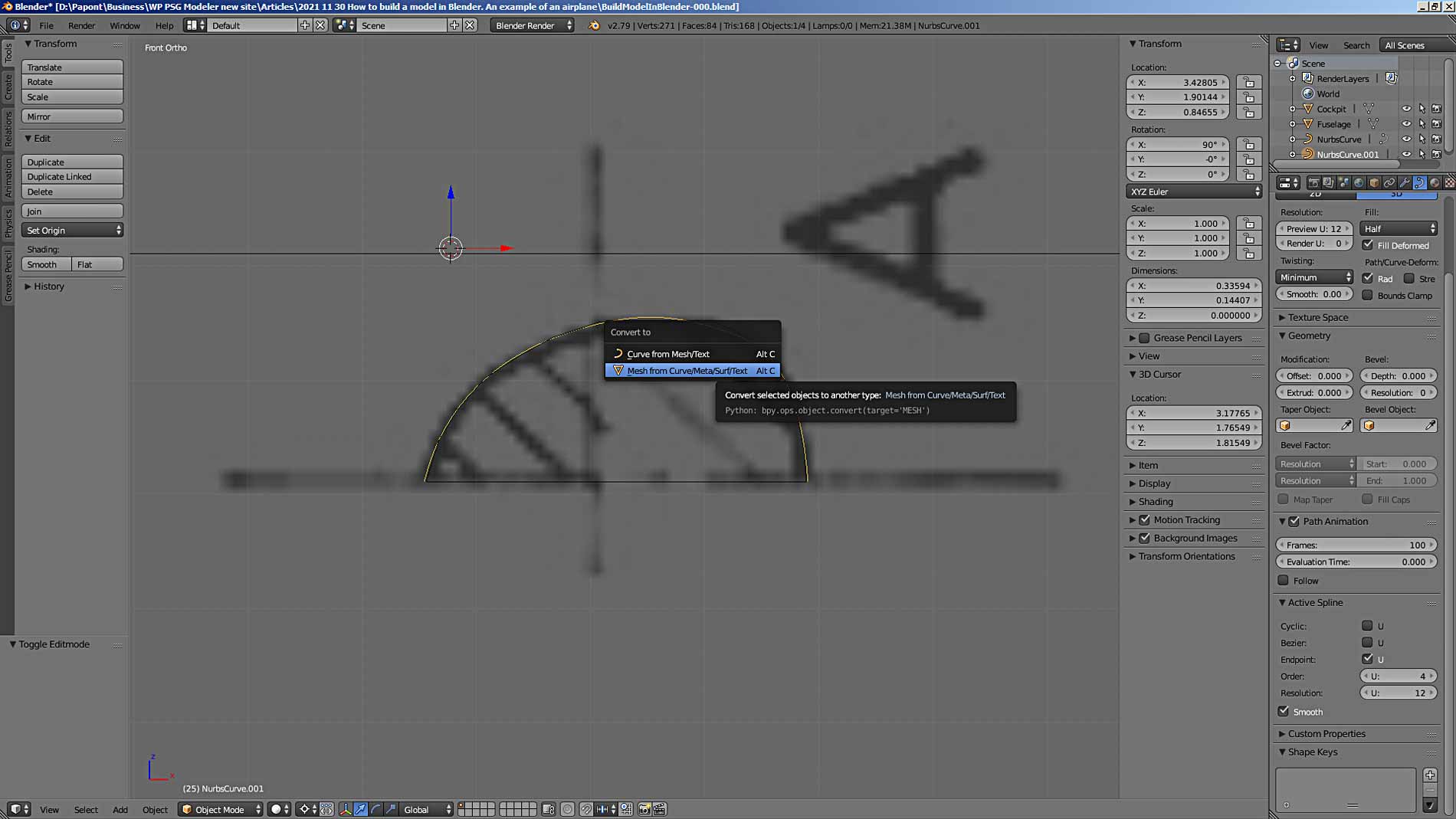
I will execute the command Alt + C for the curve. This will create a mesh from the curve.
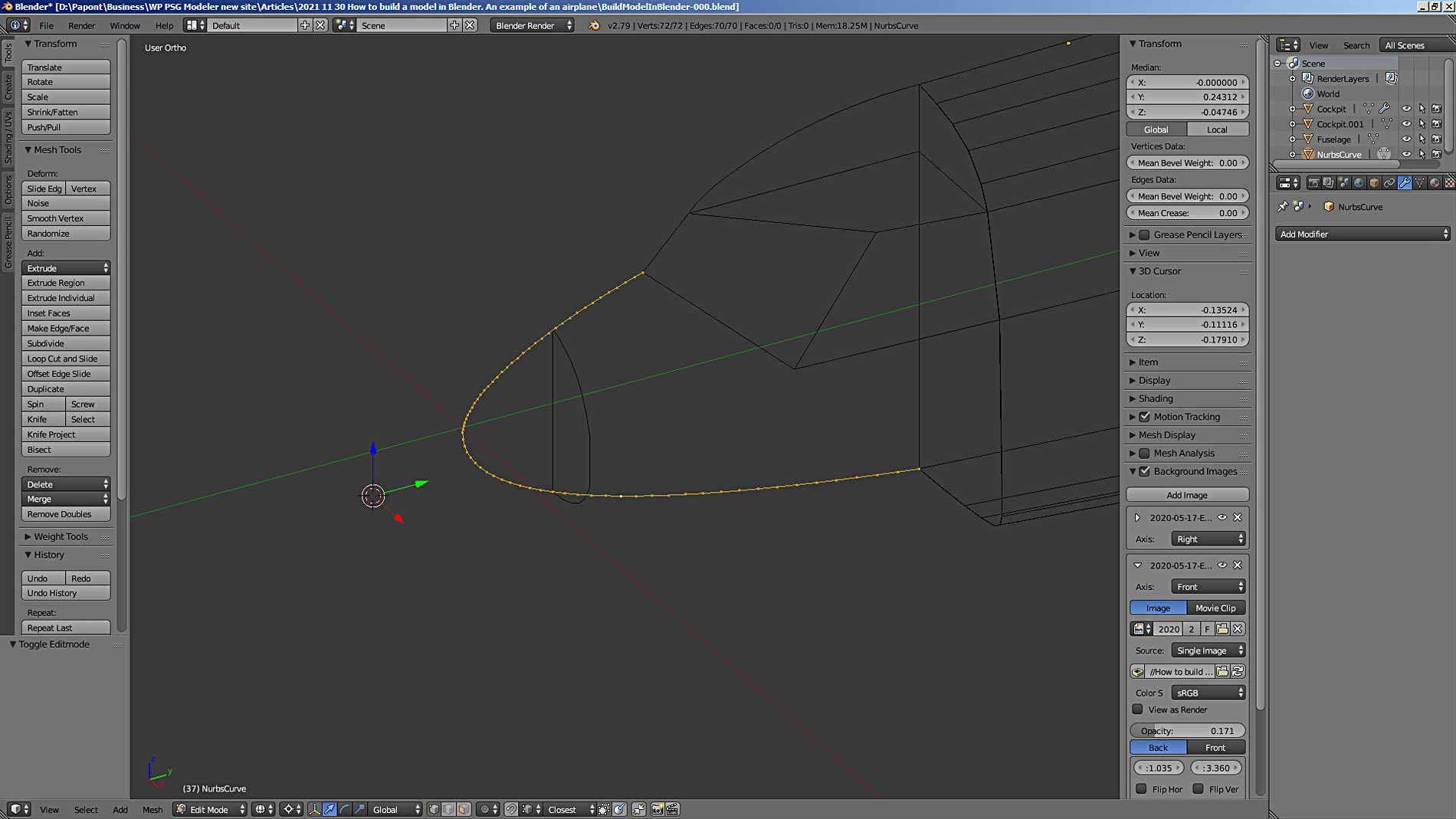
You notice that the mesh for the upper nose contour and the mesh for the lower curved contour mark as separate objects. They can be merged by merging a common vertex located at the origin (0, 0, 0). Vertices are combined into one by executing the Alt – M command, which also has several options. See for yourself, everything is simple and clear there.
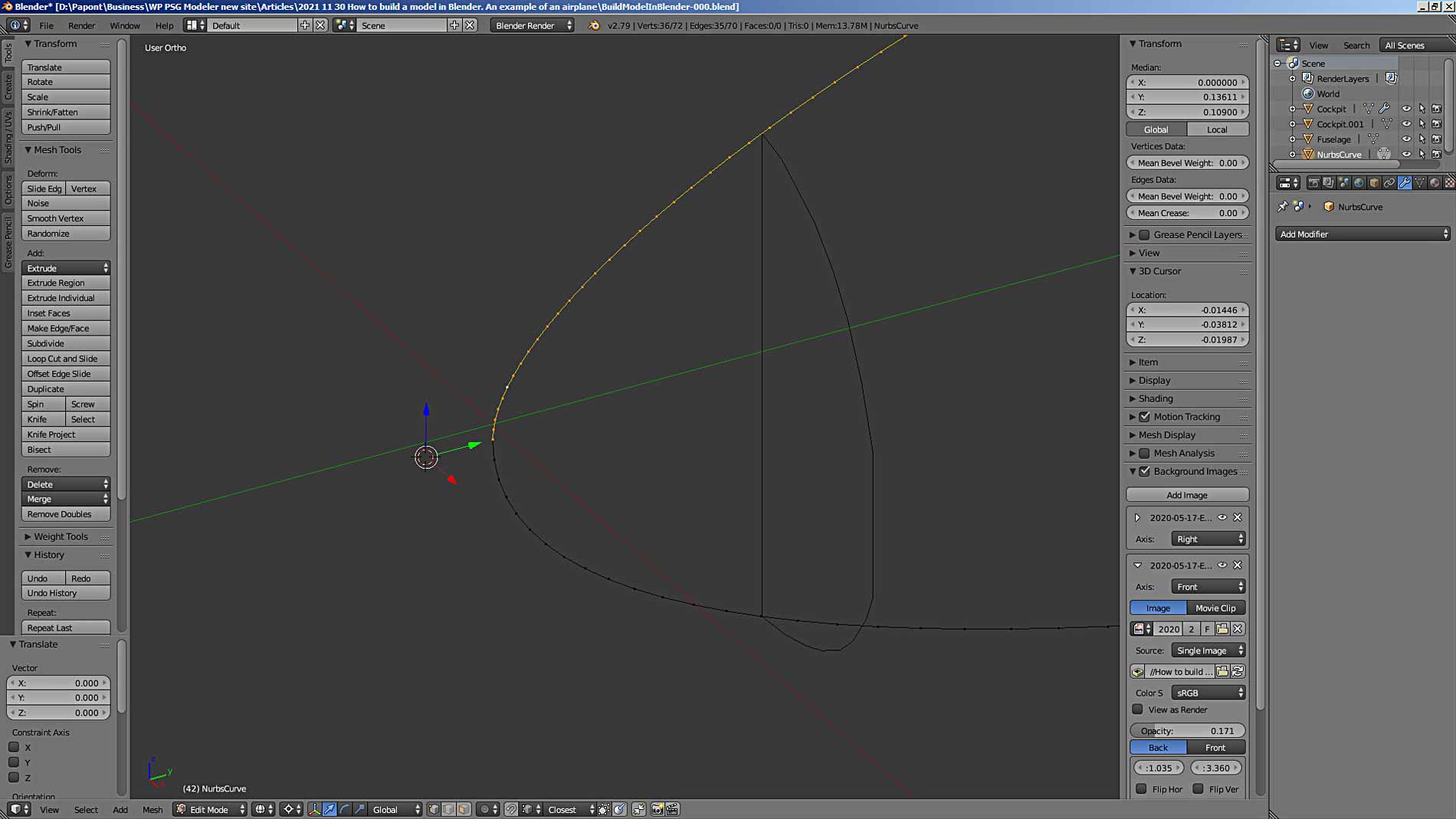
I again selected only the mesh of the upper curve and marked with the 3D cursor those points that need to be merged into one. A green arrow points to them.
Now we need to select both designated vertices. Since they coincide in space, they look like one. Select them with the command of mass selection of vertices by pressing the C key.
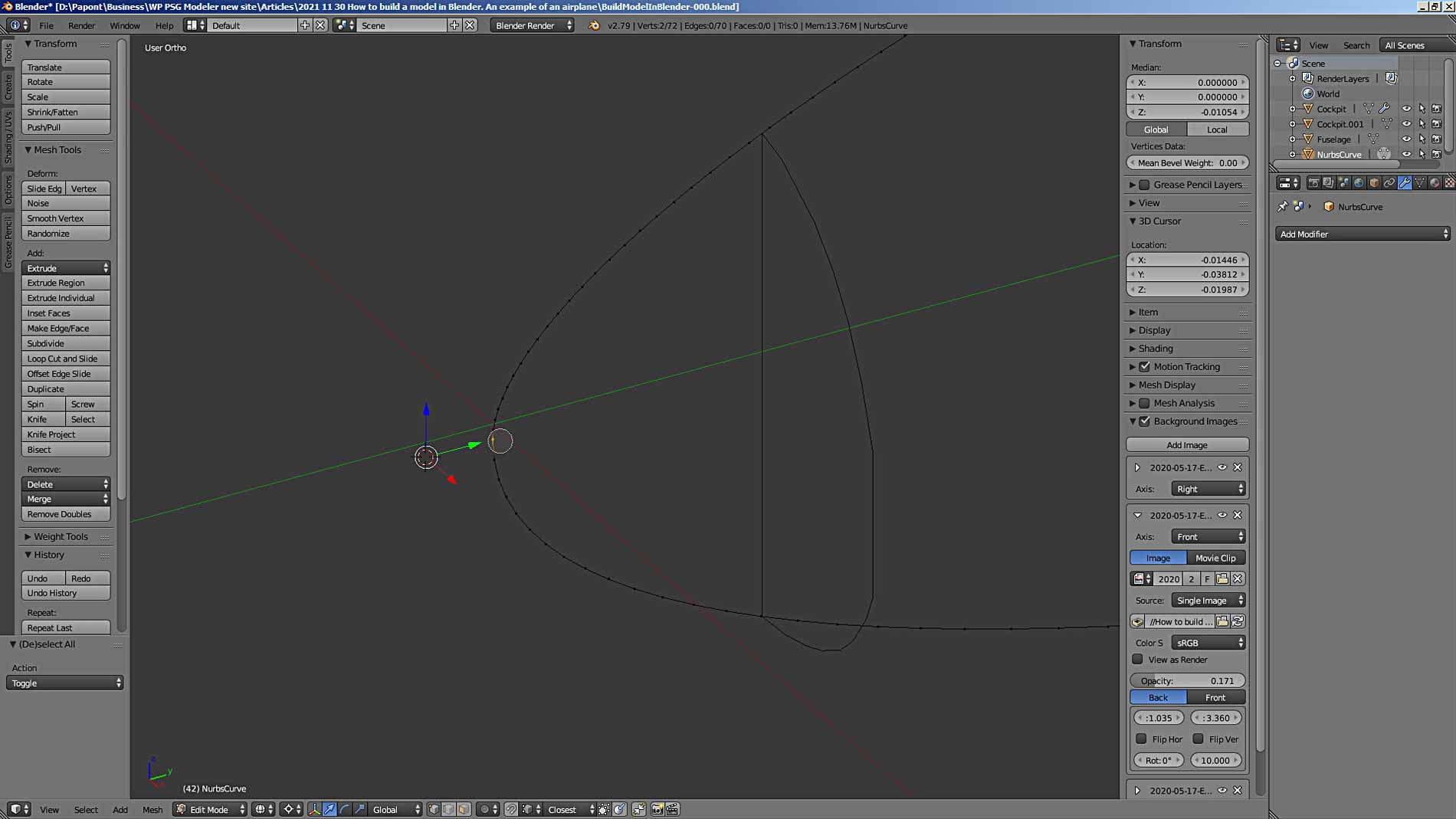
Then we’ll use the vertex merge command.
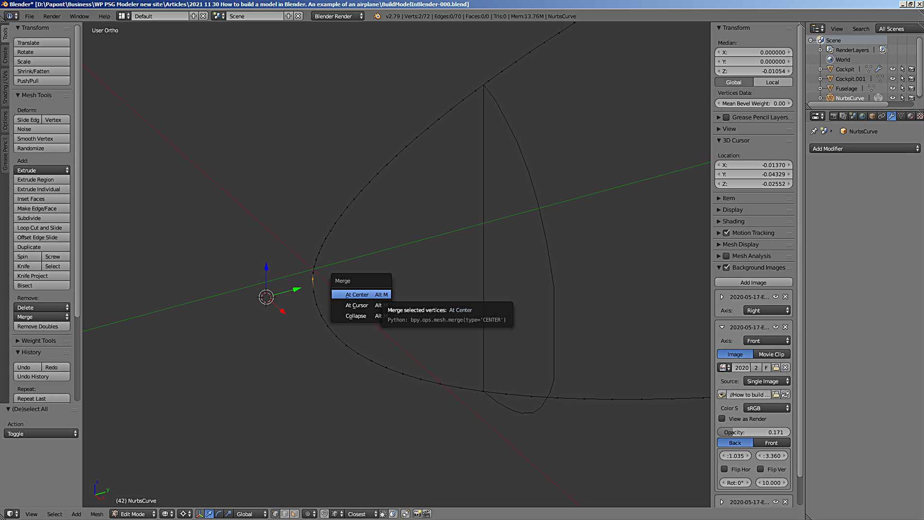
Since Blender knows the vertices are the same place, he offered me three options to choose from. I select At Center. When the vertices do not match, then they can be combined into one according to different rules. Look command, everything is clear there without long explanations.
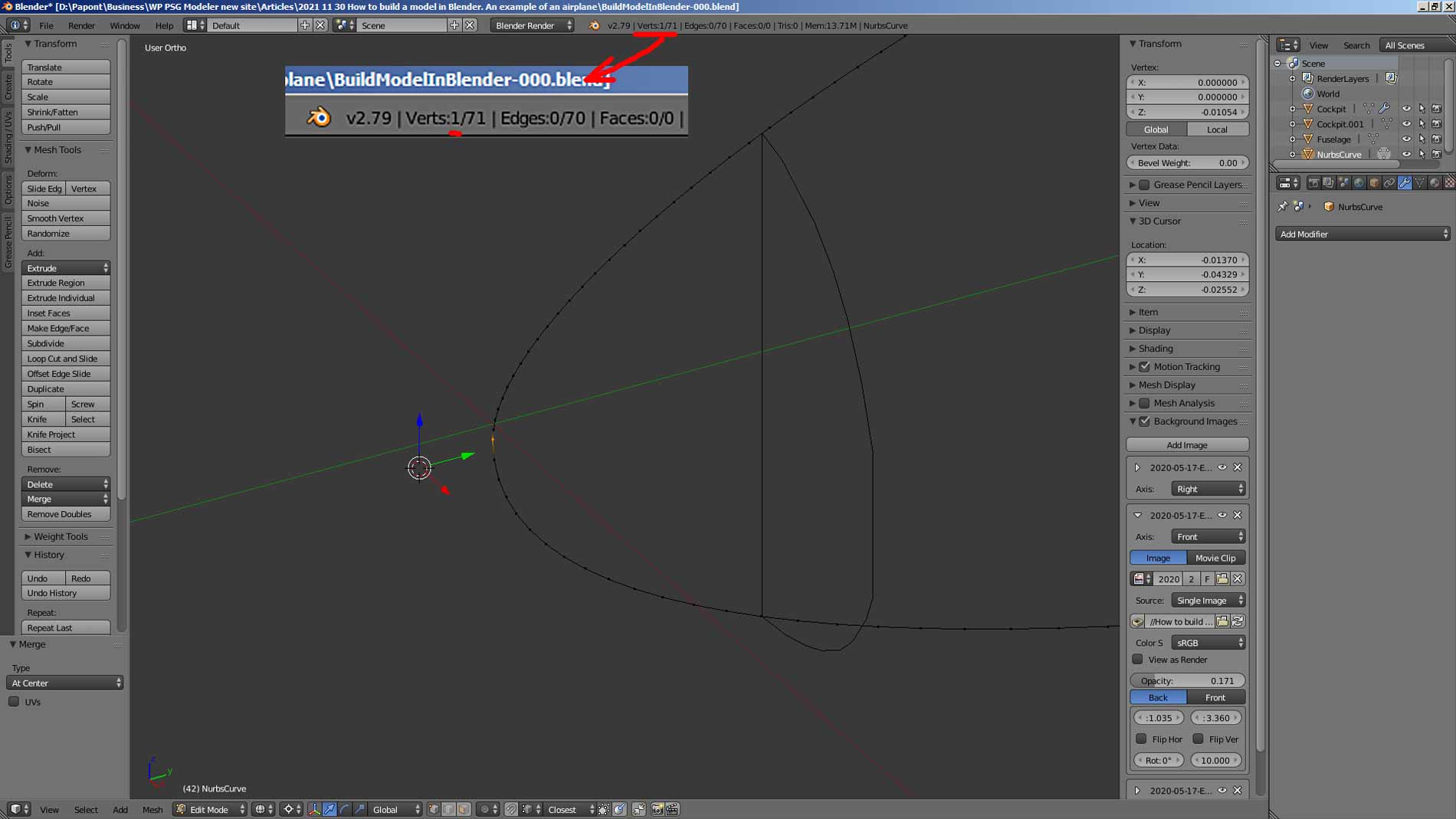
To check if the vertices have merged, you can look at the info bar at the top of the main Blender window. There, when you select objects, in our case – vertices, it shows how many vertices are selected from their total number. Before the merger, it was like this:
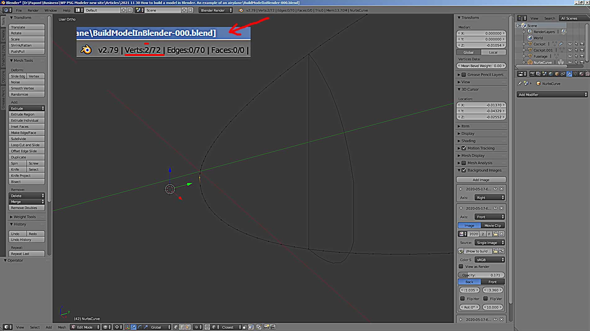
After merging the vertices, the number of selected vertices becomes equal to 1.
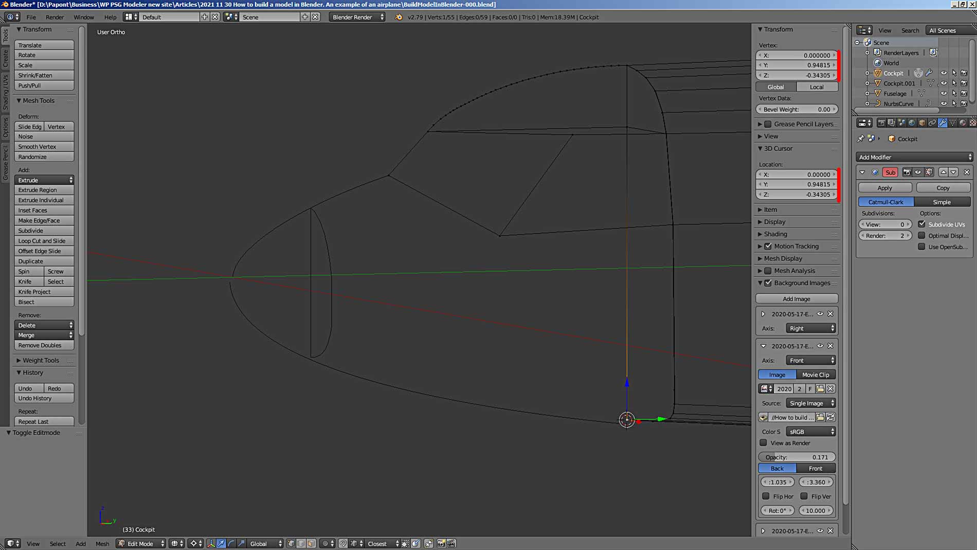
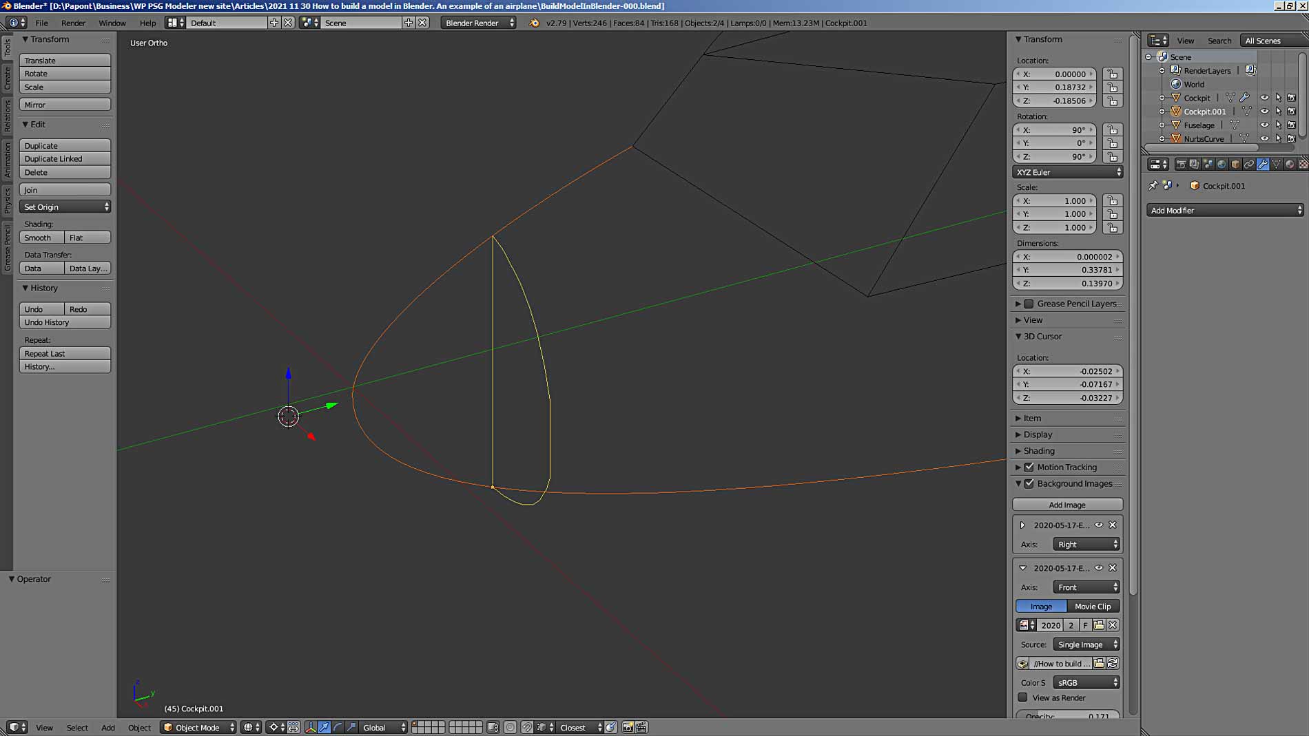
Now you need to add section A to the resulting structure. To do this, go to Object Mode and attach section A using the Ctrl + J command. First, I select both objects. The last selected part remains yellow, all previous selected parts are colored orange.
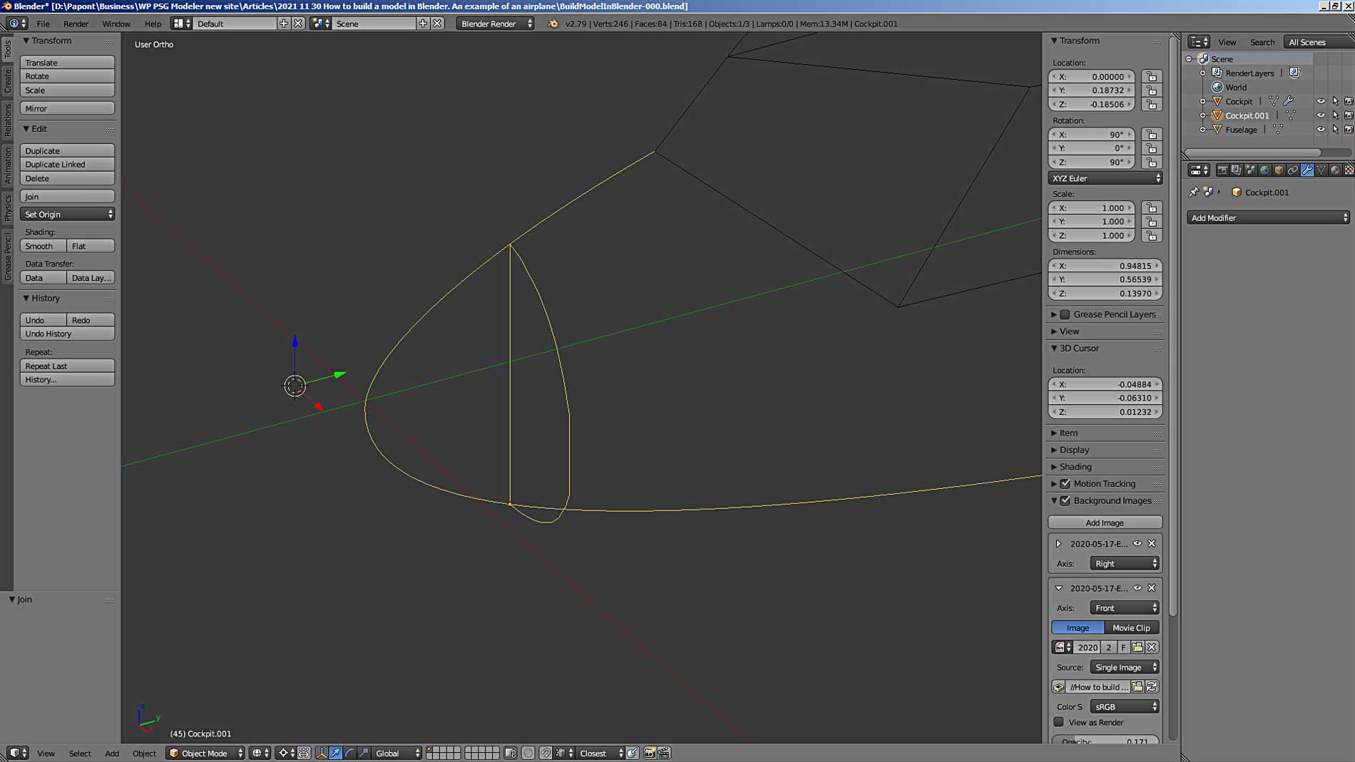
After combining, all the parts are highlighted in yellow, indicating that they are now one common part.
Perhaps, I will stop at this point. Again, this is a very long story. I don’t want to complicate further. So let’s continue next time.
To be continue…