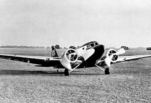
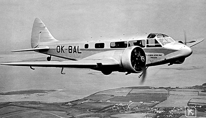
Let’s take a closer look at the shape of the nose of the aircraft. Let’s open the photo with the nose of the aircraft again.
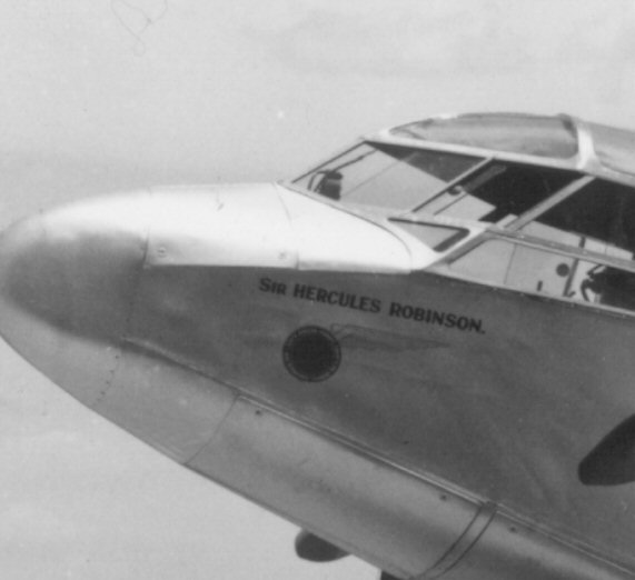
We see that the nose fairing has an elliptical shape. The transition of the vertical side of the fuselage to a fully elliptical shape is clearly visible.
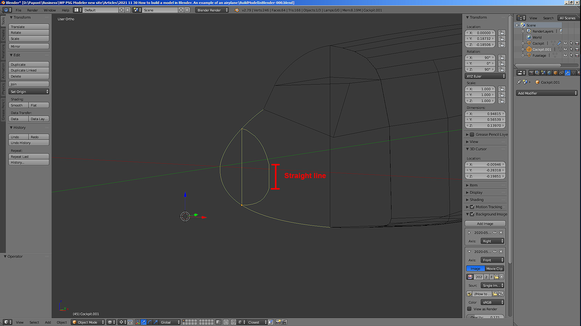
I need to turn section A, which has rectilinear vertical parts along the sides, into a completely elliptical one and smoothly reduce its dimensions to zero as it moves to the very tip of the nose. This can be done using the Extrude command. I will be extruding section A towards the nose by a small step and then scaling it to match the size in the Side view and the Top view. Thus, I will begin to stretch the skin of the aircraft on the existing frame. That is, on section A and the contour of the fuselage in its diametrical plane.
Let’s do that.
Now we need to switch to Edit mode.
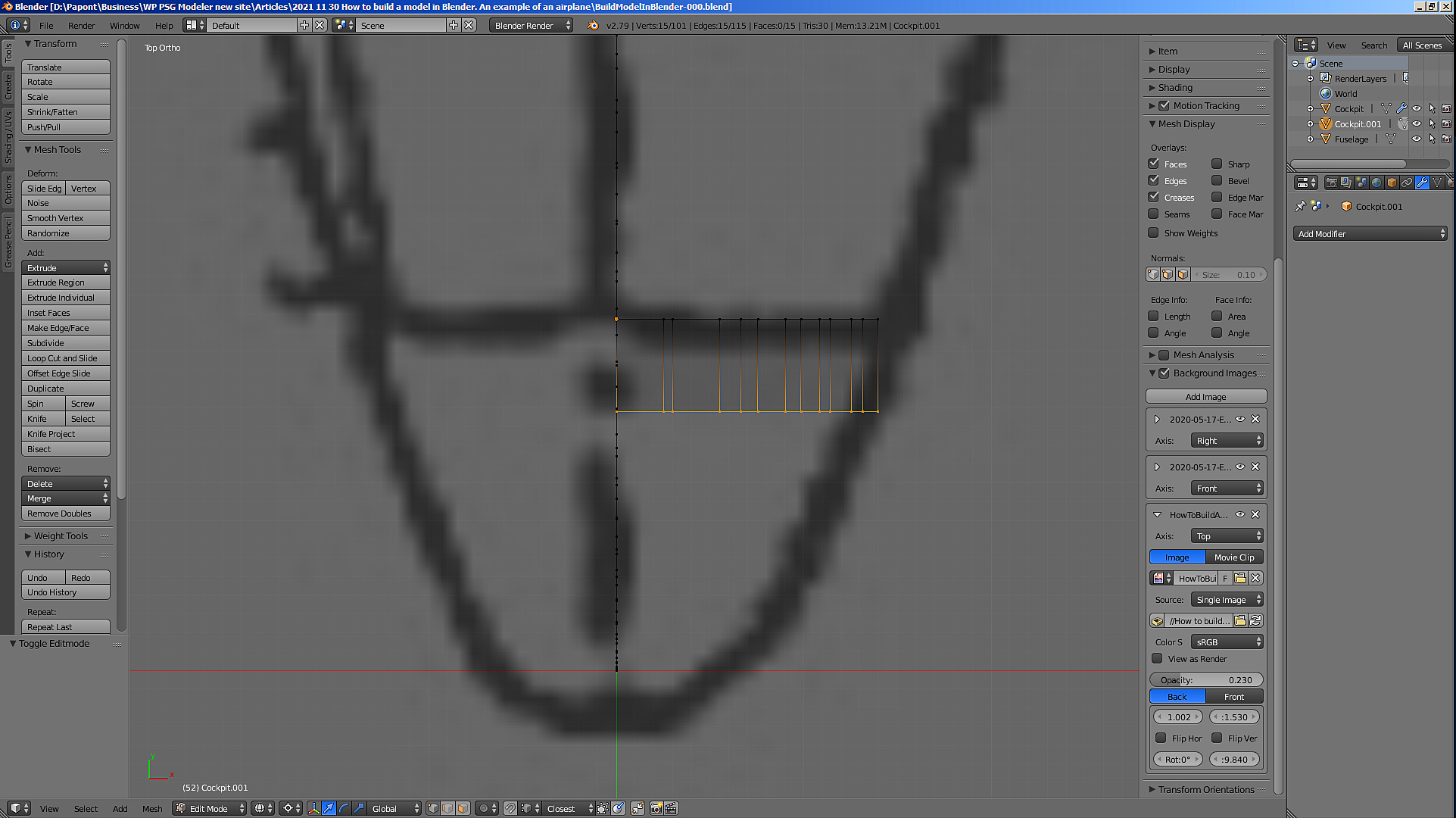
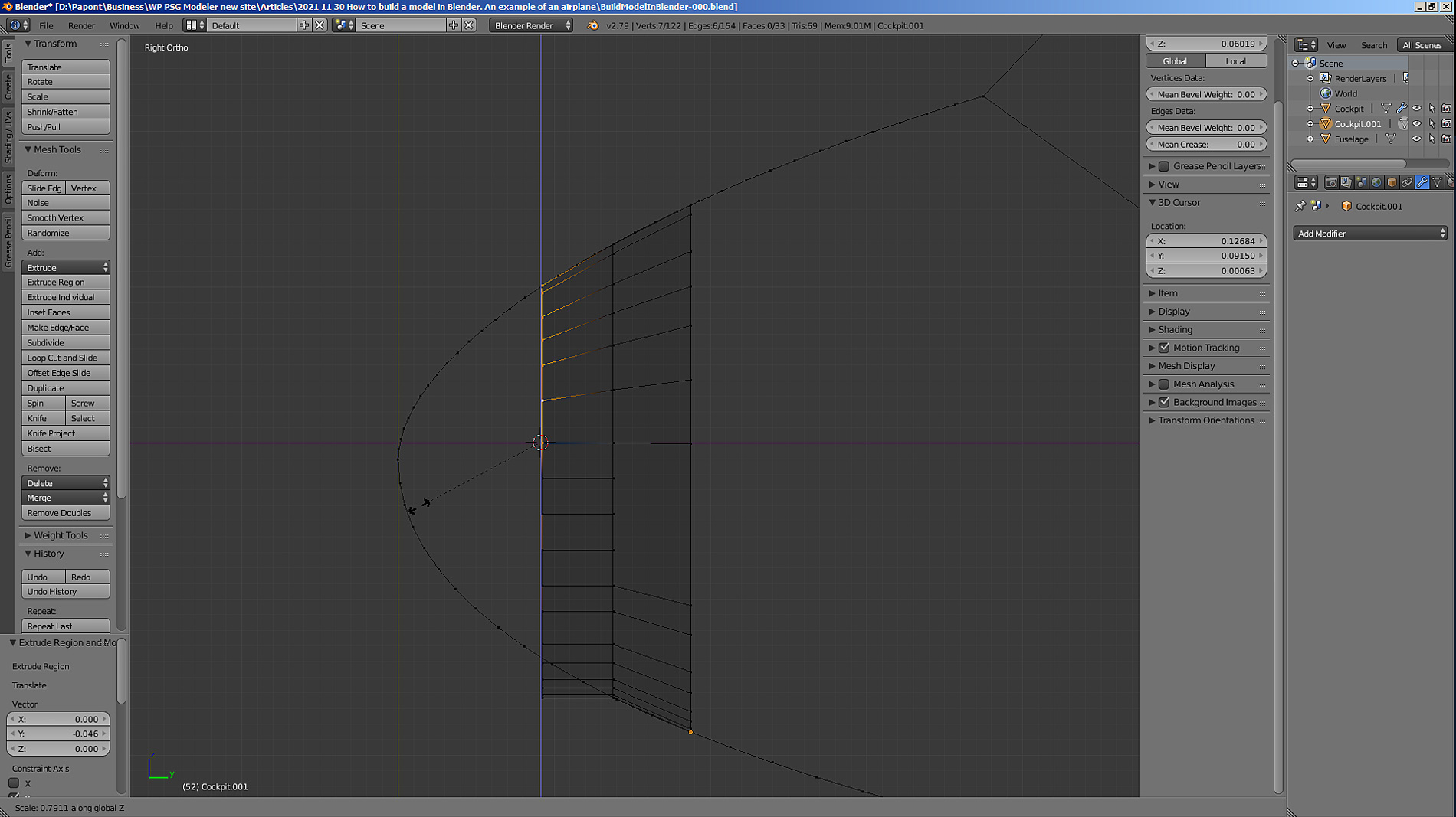
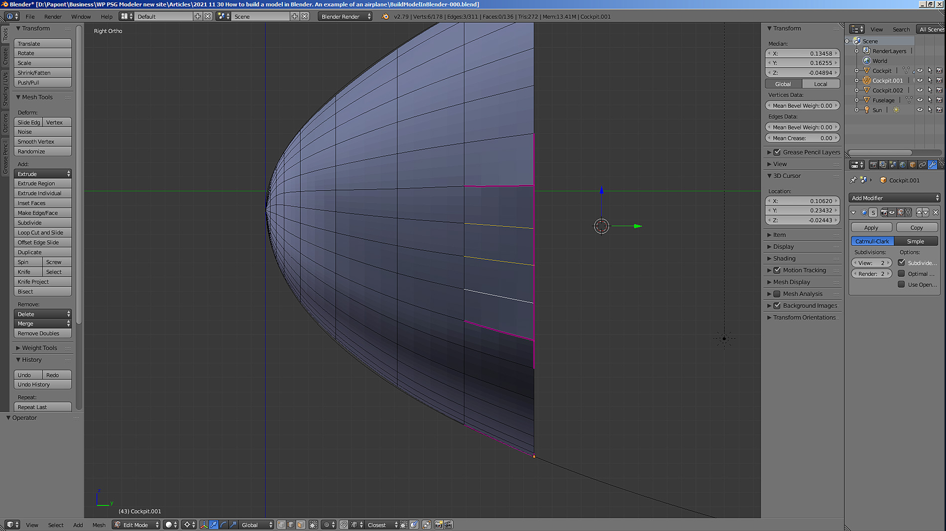
Let’s take a side view. Now we need to apply the extrude command to section A. Let’s do it.
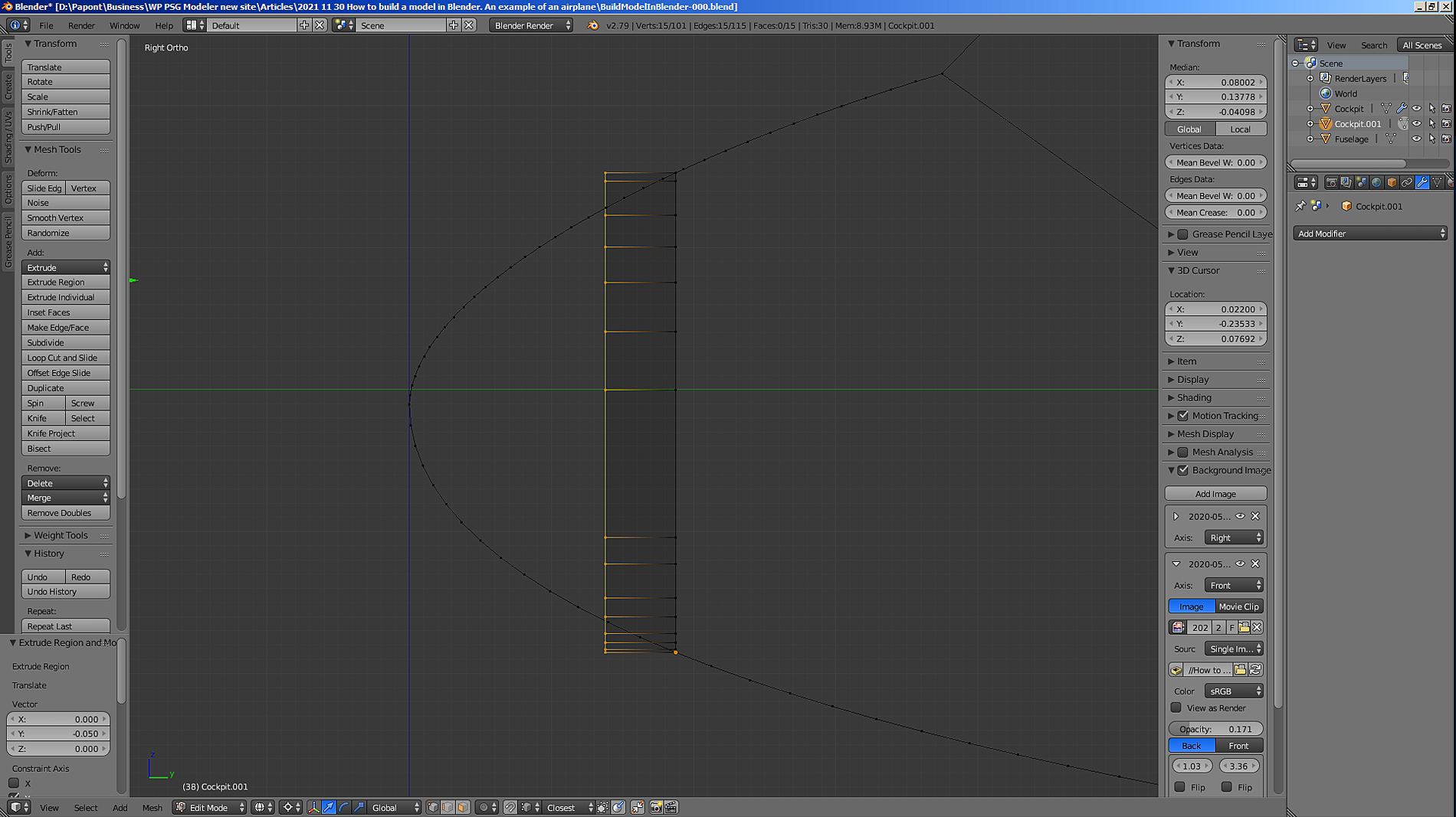
Next, you need to scale the resulting section in height. Let’s apply the Scale Z command. I will change only the height of section A.
I put the 3D cursor approximately in the middle of the height of section A and scale the section in height.
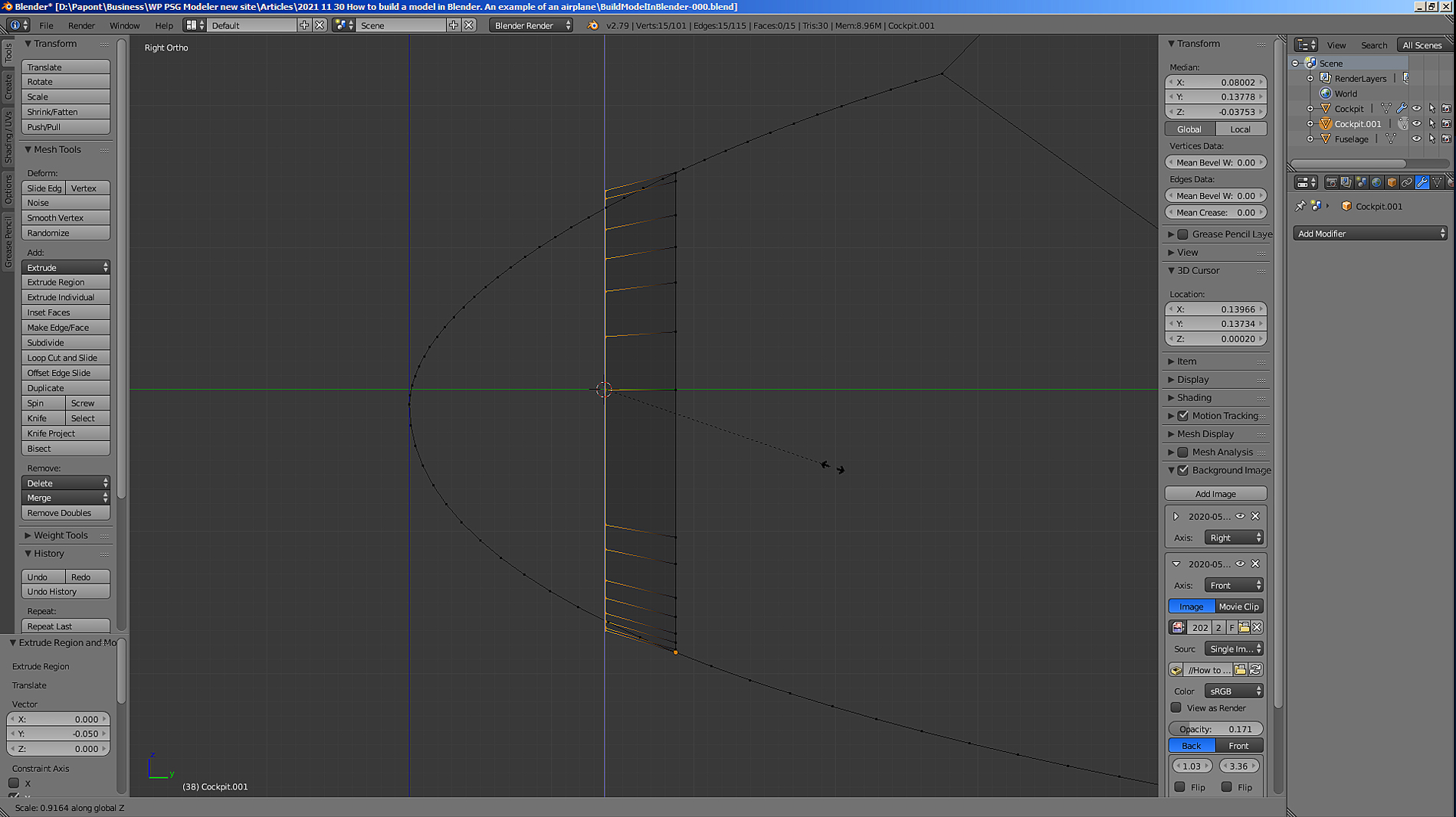
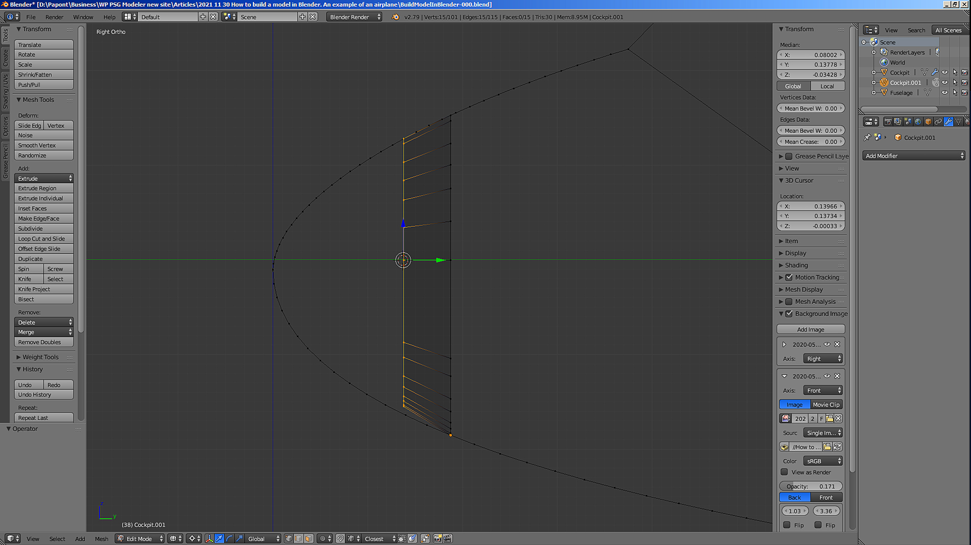
The upper part of the extruded section comes to the desired point. The lower part of the extruded section A must be corrected. To keep the top fixed and move only the bottom, I move the 3D cursor to the topmost section of section A. With this position of the 3D cursor, only the bottom will move when zooming. Let’s put it in its place.

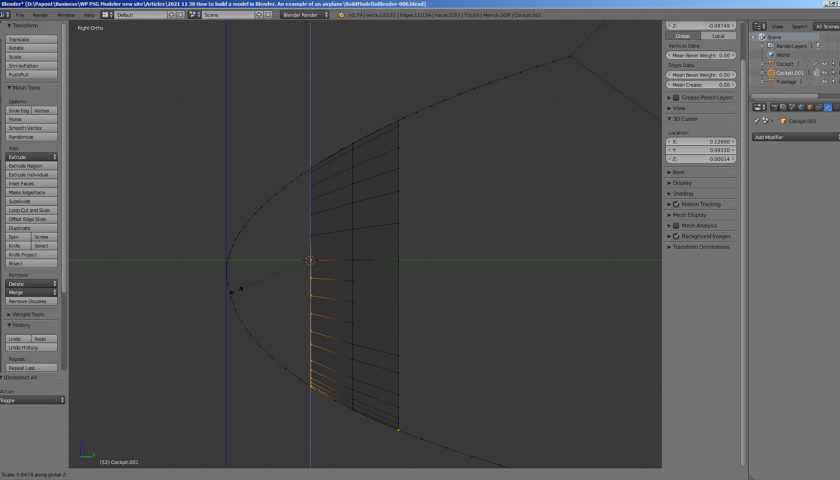
Let’s see what happened.
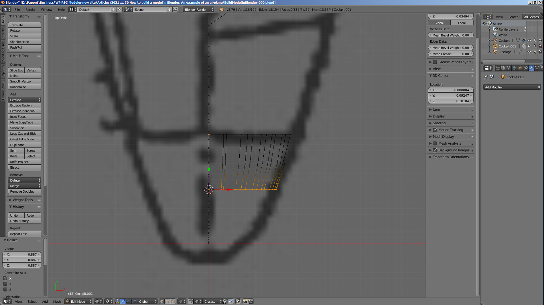
Now let’s look at the top view.
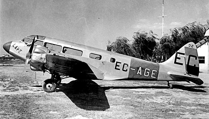
I have already said that the pictures of the aircraft are bad, and it is necessary to build a model of the aircraft on the basis of common sense. Common sense tells us that we need to perform the same transformation that we did in the side view. We scale the section in the top view, that is, along the X axis.
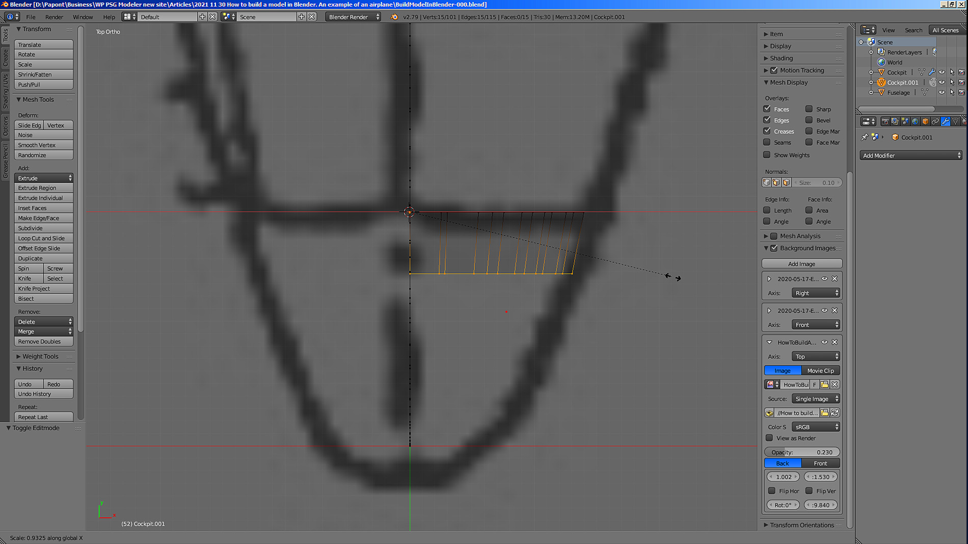
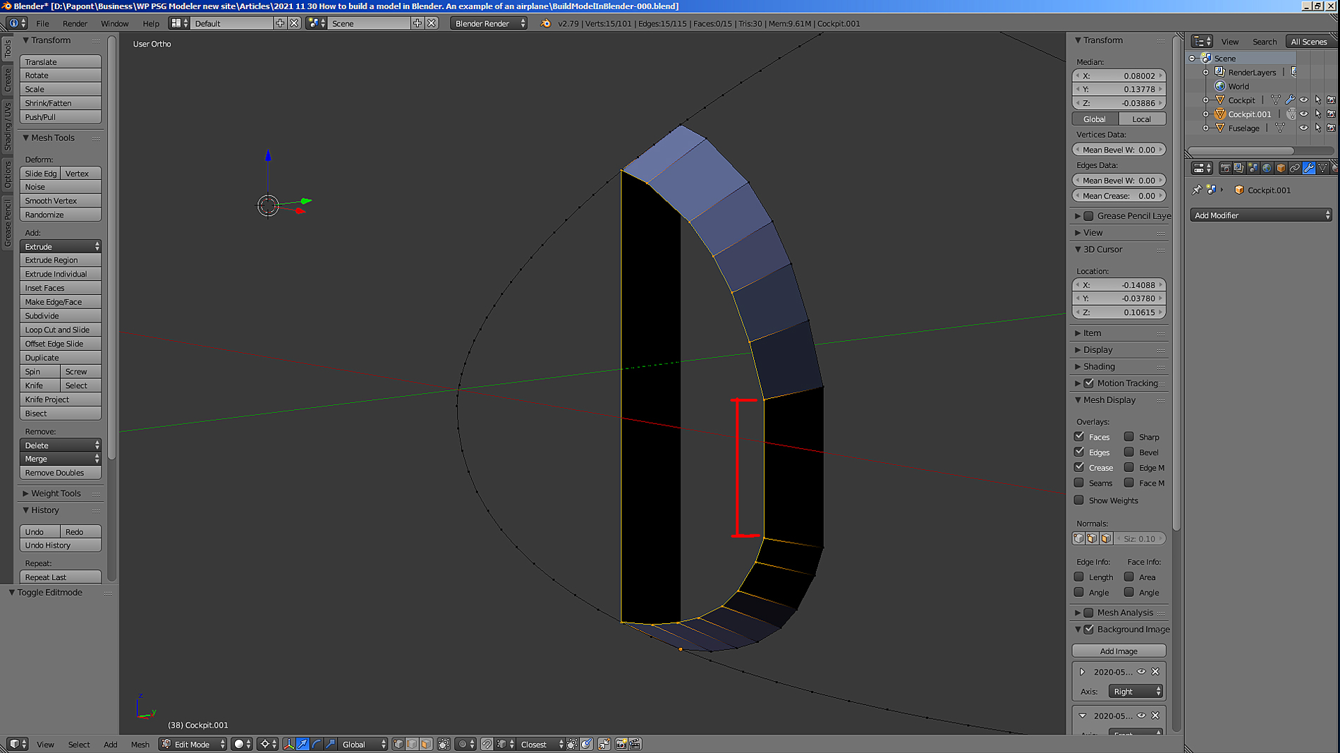
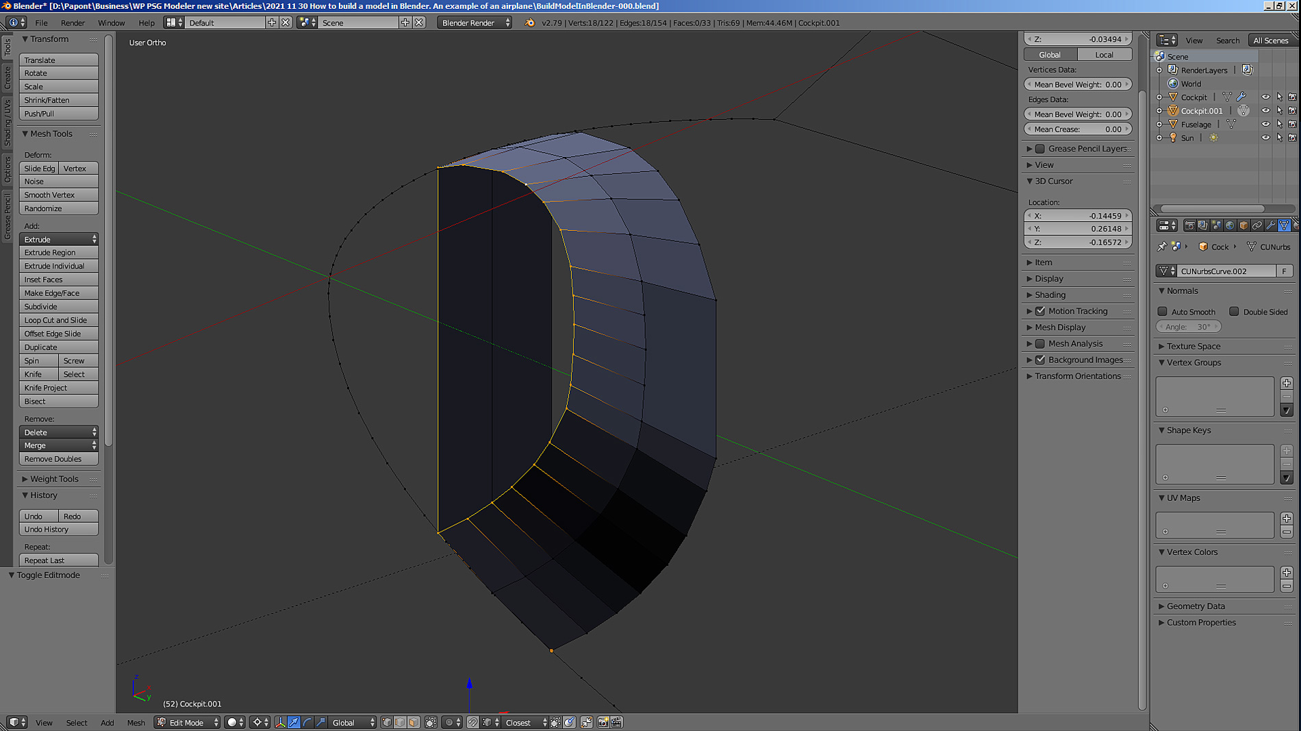
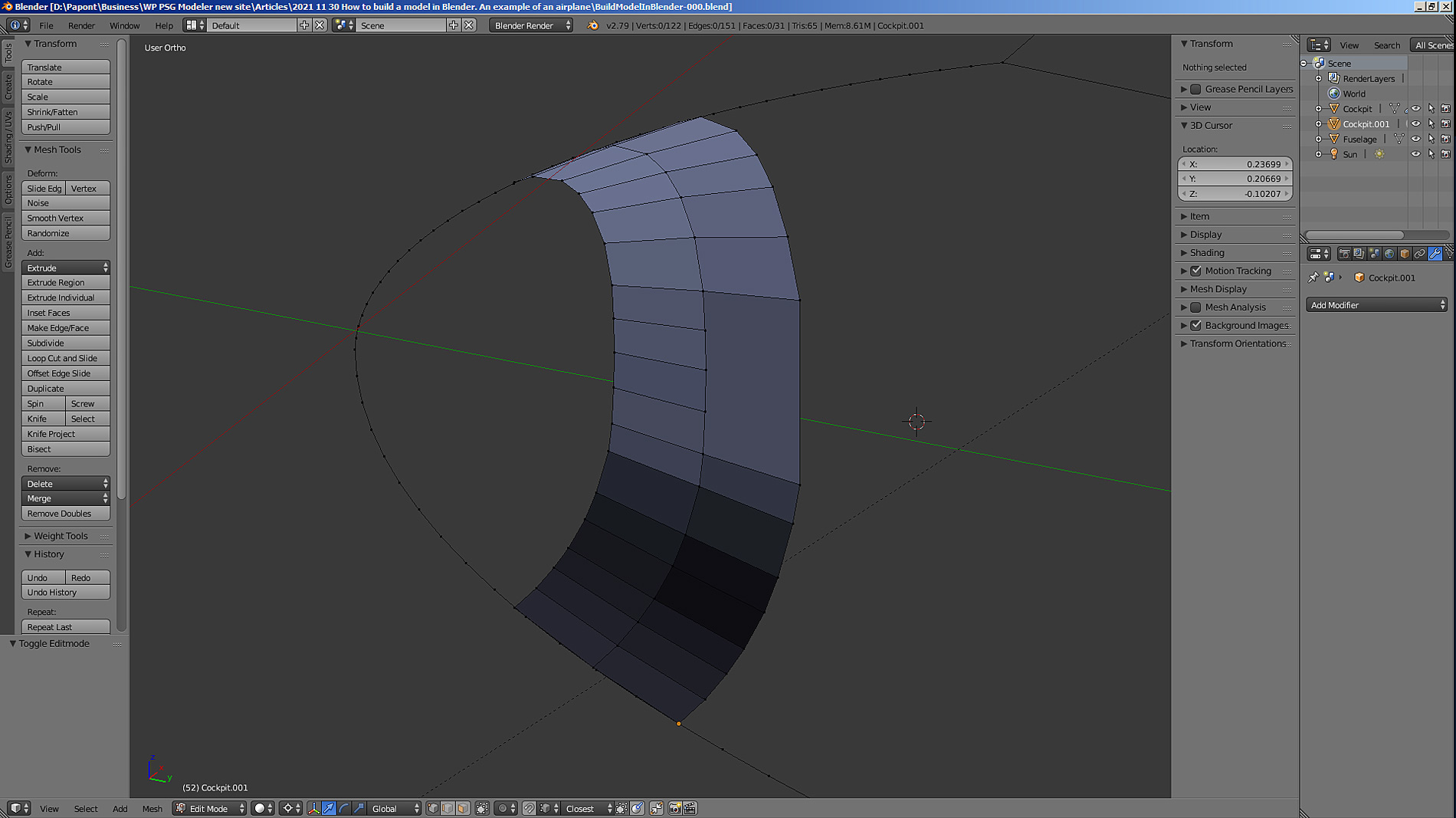
I ended up with an annular, conical segment of the aircraft skin.
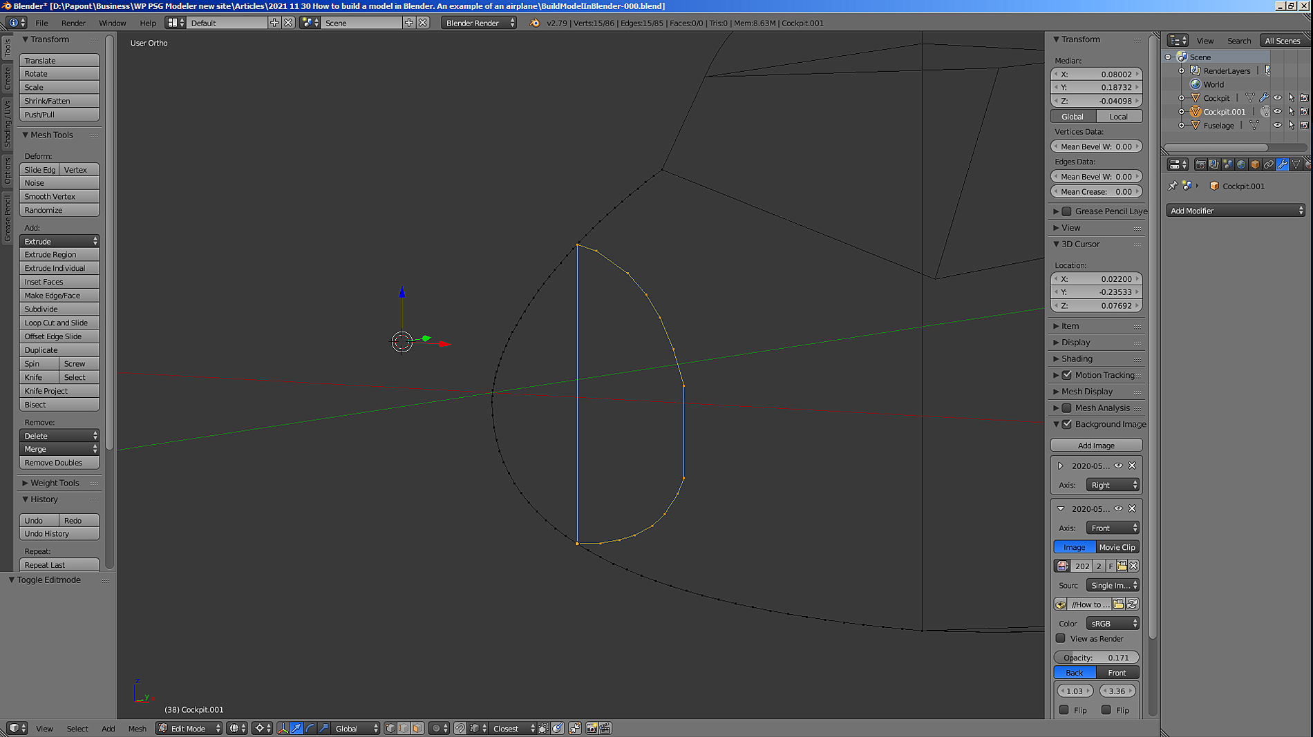
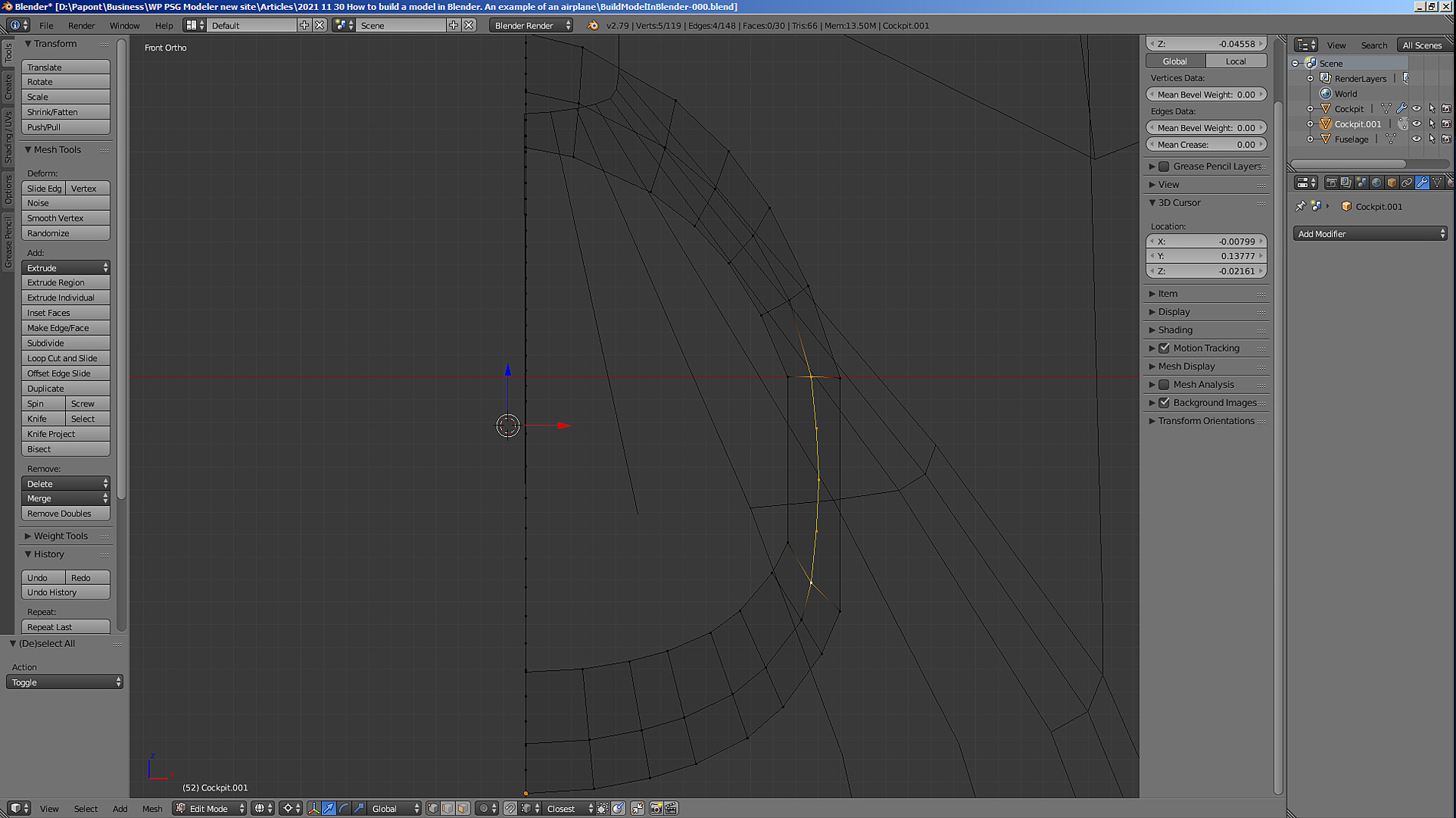
Now we need to make an elliptical straight section, which was copied when extruding. In order to give this rectilinear section curvature, you need to add several vertices to this segment. Select the extreme vertices of the straight section and apply the Subdivide command to it twice. Then we shift the points in pairs inside the section.
Then you need to repeat the operations done and build the next similar segment. Therefore, we get to the very end of the fuselage and get the nose of the aircraft.
Let us build the next skin segment. Here it should be noted that the shorter the width of the segments, the smoother the contours of the bow. And the second remark. In order for the mesh to be “correct”, that is, to evenly cover the surface of the fuselage, we will make its middle line remain on the Y-axis (green axis). To do this, you will have to scale half the section. Separate top, separate – bottom.

Let’s start with the side view. Using the “Extrude” command, we extrude a new section, which we then scale in width and height.
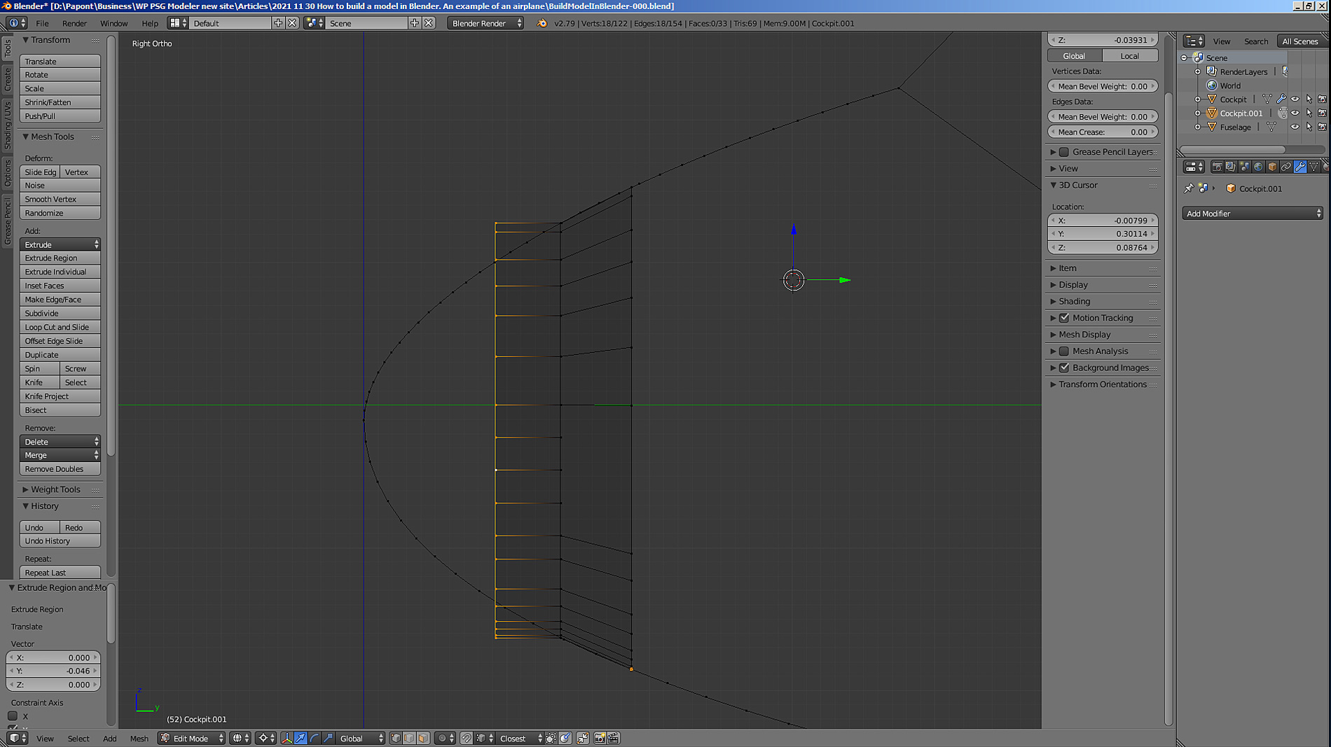
Now extrude and scale the section in the top view. Here you can scale the entire section at once.
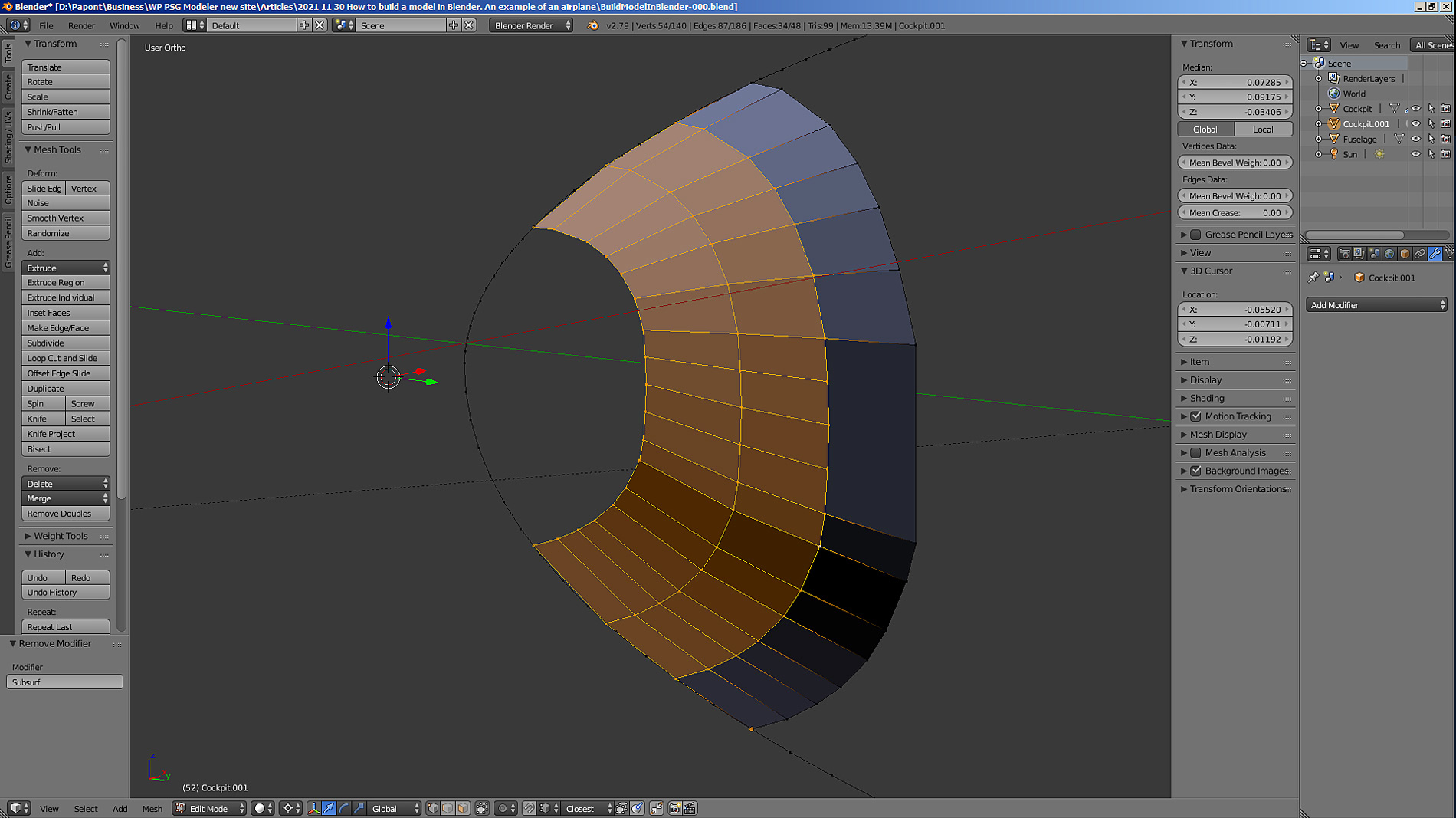
Let’s see what happened.
Now you can see that we do not need vertical faces in the diametral plane. Let’s delete them.
We repeat the cycle of extrusion of the next segment and its scaling. We get the third segment.
Let’s go ahead and take the next step.
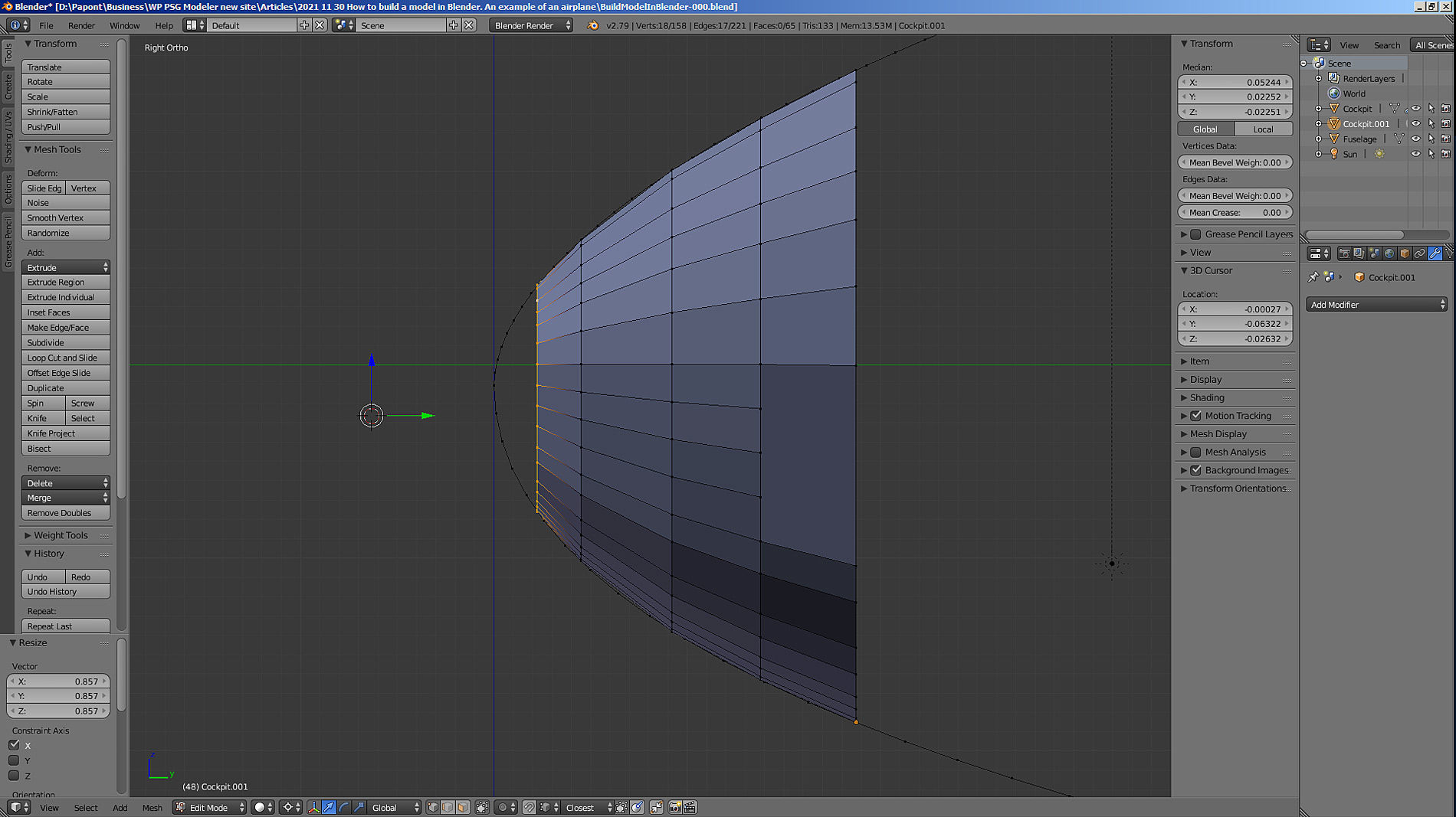
Let’s finish building.
The last segment is built very simply. It is necessary to set the 3D cursor to the extreme point of the forward part of the fuselage and press the key combination S + 0. In this case, all points of the previous segment must be connected into one. In the point where the 3D cursor is placed. If the point “goes” to another place, then it should be put in the right place by moving along the Y axis. The result is such a nose, as shown above.
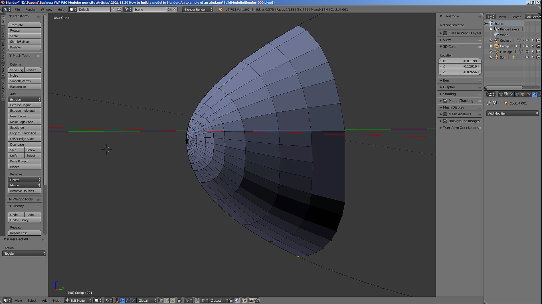
If you try to smooth the surface, you get this shape.
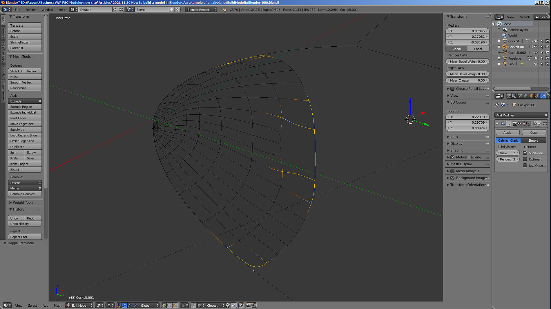

I applied the Sub Surf modifier. The picture shows that the nose has become completely smoothed. But, in the photo in this place, there should be two “sharp” edges. They need to be restored. In addition, the upper and lower corners of the bow are rounded. They need to be made sharp.
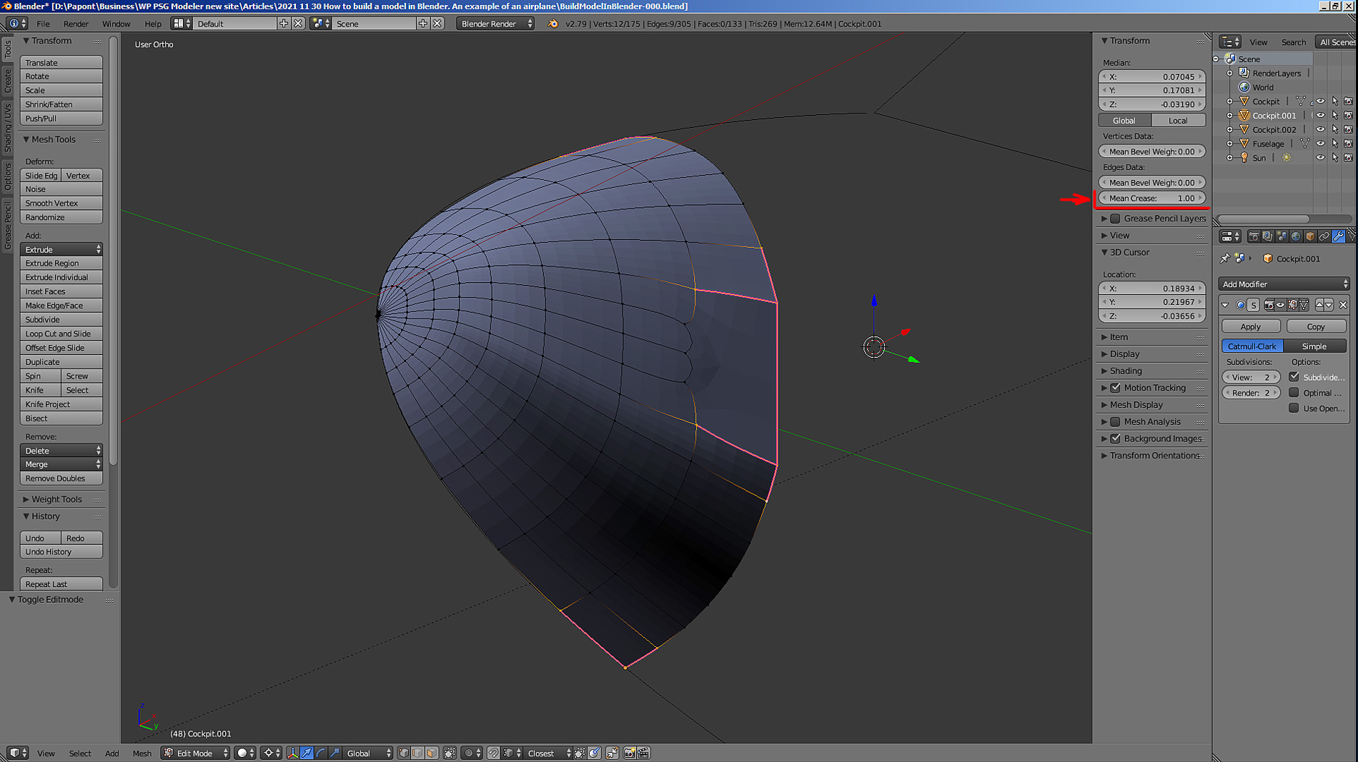
This is done with the Crease command. It is necessary to select the vertices adjacent to the corners, as well as the vertices on the edges, which should become “sharp”.
Now let’s apply the Crease command. The window with the parameters to be changed is located at the top right of the Transform sidebar. Set the value of the parameter in the Mean Crease window to 1. We get “sharp” edges and corners.
There is one detail that does not suit me: this is the “wavy” shape of the vertex arrangement.
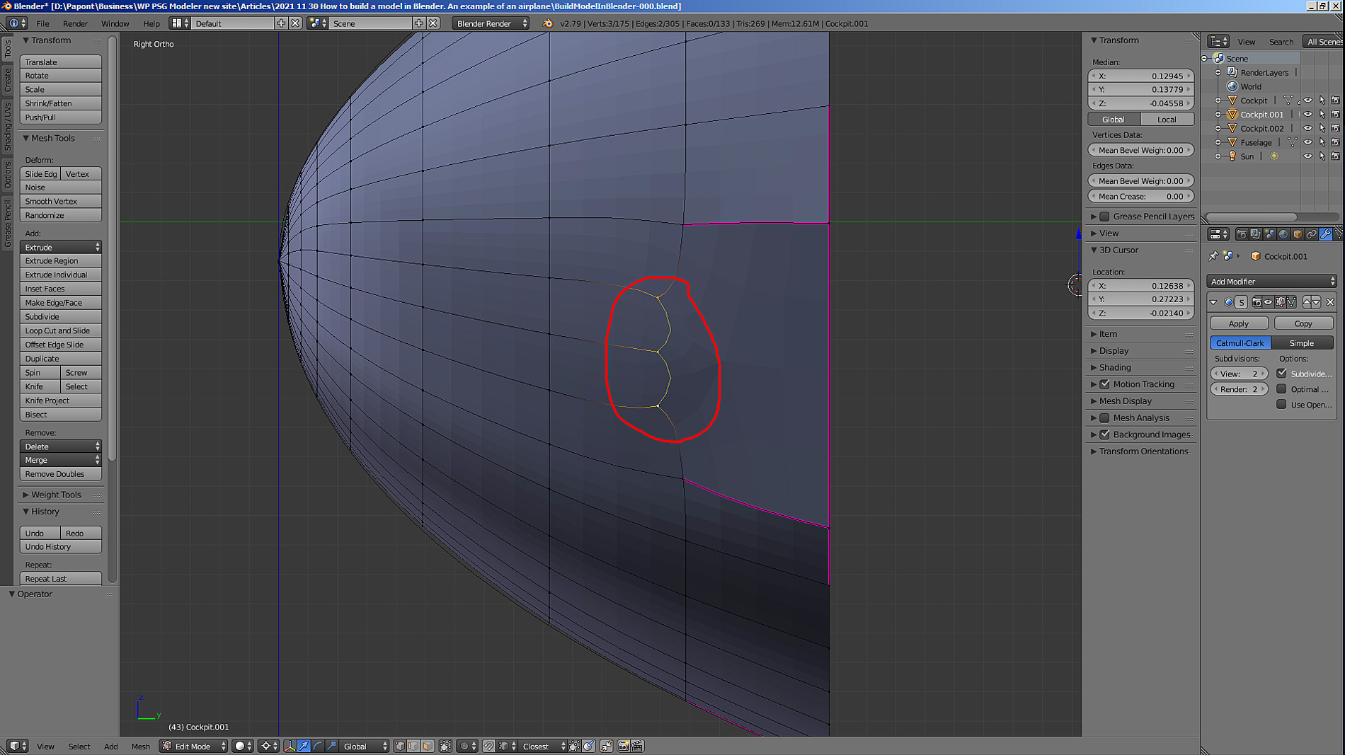
When I applied the Sub Surf command, these vertices, having no “counterweight” on the right side, were “stretched” by the neighboring vertices to the right. I already mentioned that the Sub Surf command stretches the net, it becomes “rubber”. In this case, the vertices need a “counterweight” on the right side. Let’s connect the vertices that have left their places with rectilinear edges with horizontal edges. This can be done using the Knife command.

It turned out crooked. But, this is a consequence of the mesh stretching that the Sub Surf command gives.
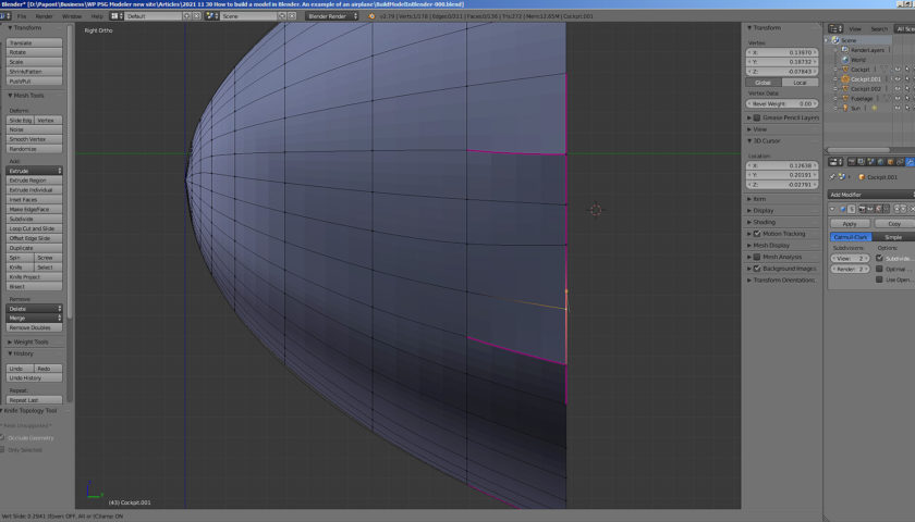
We put the remaining edges in place, and the grid should balance and take the “correct” shape.
It didn’t turn out perfect. Those vertices whose position does not suit you can be put in place using the very useful Shift + V command. This command allows you to move a vertex along the edge it lies on. This way we can change the position of the vertex without disturbing the shape of the grid.
Fix the position of the vertices with the Shift+V command.
As a result of the work done, we got quite a decent nose of the fuselage of our aircraft. Let me remind you that the absolute size of this part will be very small. About 15 mm in height. The result obtained is quite enough to present this part of the fuselage as having smooth, streamlined shapes. More precisely, the form here does not need to be done.
Since I again wrote too long text, I thank everyone who had the patience to read all this to the end and suggest continuing work on the rest of the fuselage next time.