Last time we stopped at the fact that we made one section of the fuselage of our aircraft and agreed that you will do the rest of the work with the fuselage yourself.
Let’s check out our homework.
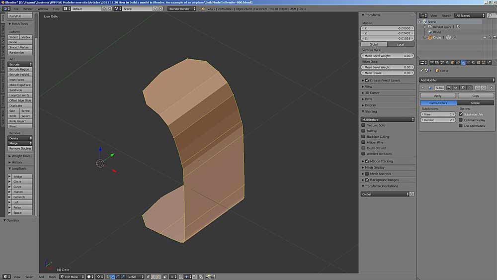
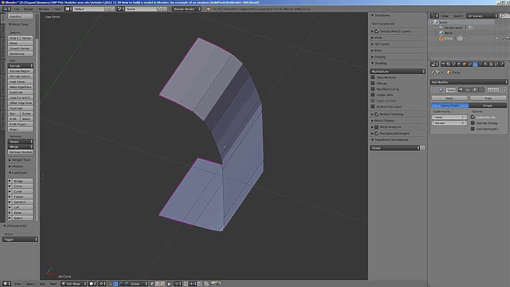
We still have one question unresolved. After applying the SubSurf modifier to the fuselage section, its edges were stretched like rubber and received rounding. This needs to be fixed. This is done using the Crease tool. We had such a picture.
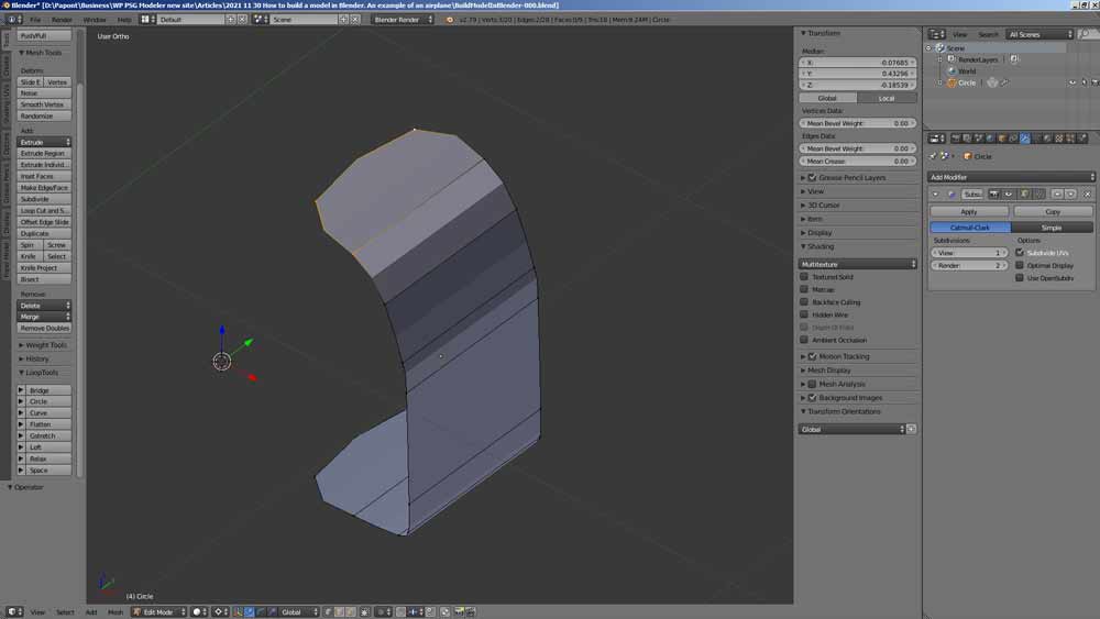
Mark the points of the rounding to be corrected.
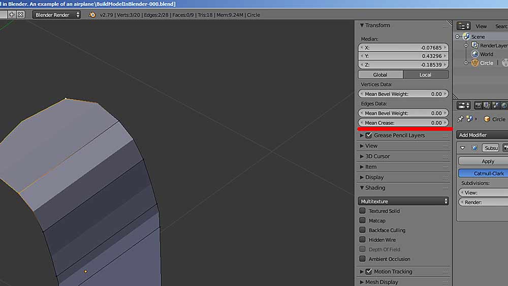
Now, at the top right, we find the Mean Crease parameter in the Edges Data panel.
We put the value 1.00 there and see how the corner straightened. At the same time, it will be marked in pink.
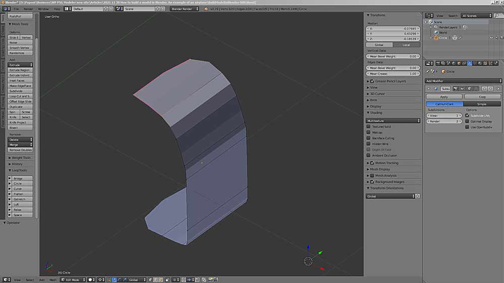
Correct the rest of the corners.
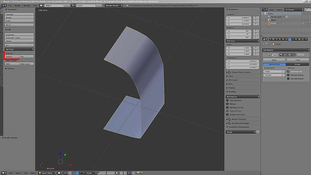
However, our fuselage section looks like a faceted one. This is just the view that Blender presents to us and which can be adjusted to match the actual view of the fuselage section model.
To fix this picture, you need to switch to the Object Mode object editing mode, then on the left side of the Tools tab, find the Shading panel and find the Smooth command on it. You will get a real view of your fuselage section.
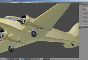
Now everything is ready to start modeling the fuselage.
At this point in the simulation, you need to decide how this work will be executed. A plan for further action should be thought out in advance. To make things easier, I will be modeling the fuselage using the old technology. Fuselage assembly from kegs-sections. At the same time, I keep in mind the fact that all sections must be either cylindrical or conical, since this method of assembly implies that a double curvature cannot be made from paper. This means that the silhouette of our fuselage will have a poly line contour.
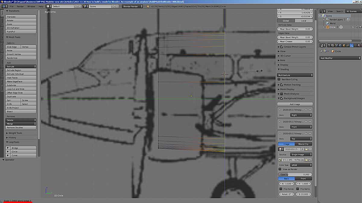
Now we need to take a close look at the cross-sectional shape of the fuselage. We will see that it has two straight parts with rounded top and bottom. On closer inspection, the fuselage roof also consists of several straight sections in cross-section. It turns out that there is no point in rounding the cross-section and applying the SubSurf modifier for this.
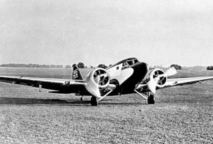
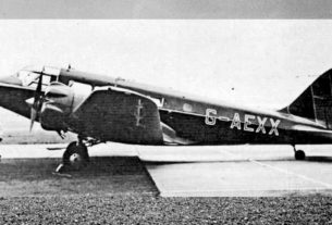
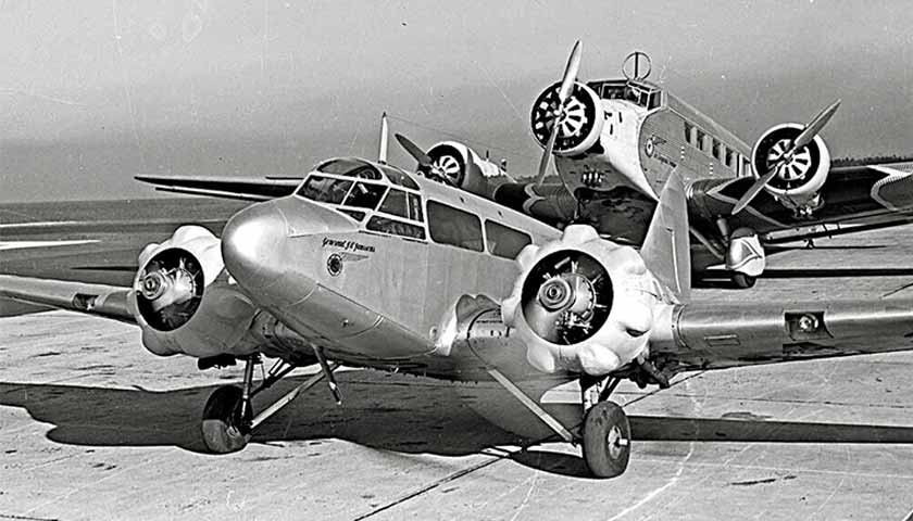
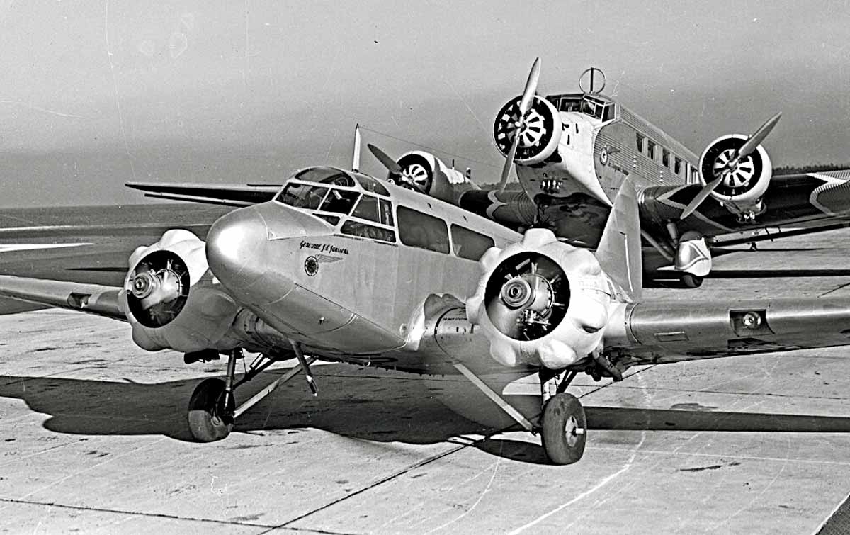
It is necessary to correct the shape of the cross-section in accordance with the shape of the real fuselage. Our drawings are very inaccurate and therefore the form of the fuselage is necessary to check by the prototype aircraft photos. One good photo will allow you to understand the shape and, with the help of logical conclusions, fill in the lack of information about the shape of the fuselage in the drawings.
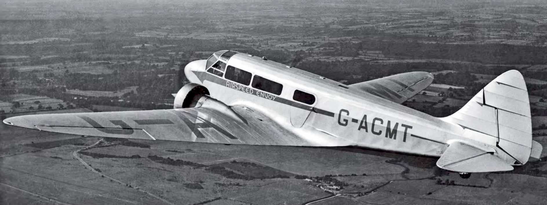
These photos give an idea of the shape of the fuselage of our prototype. The fuselage roof has five edges in cross-section, which are located along an elliptical line. Then comes the inclined side with portholes. Then the vertical wall, then the rounding, which passes into the bottom with an elliptical cross-section.
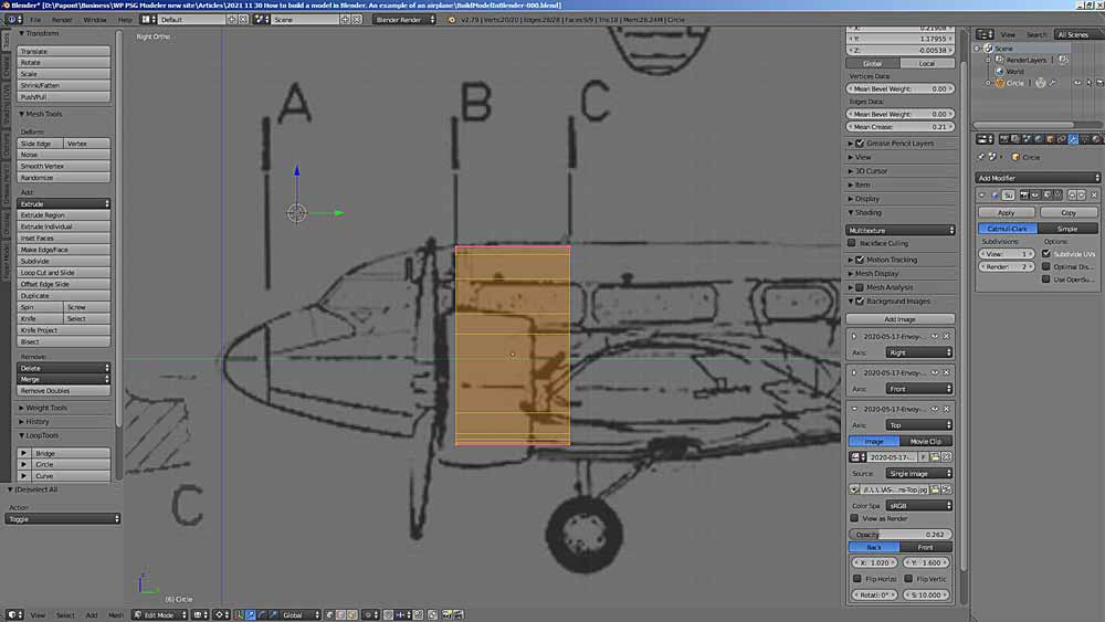
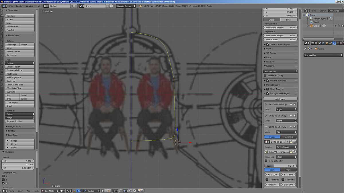
Let’s go back a bit and fix the shape of frame B taking into account what we saw in the photo. Let’s delete section C.
To accomplish this, you need to add points to the contour of frame B. This is done using the Subdivide command, which is located on the Tools tab, Add panel. Let’s get this shape.
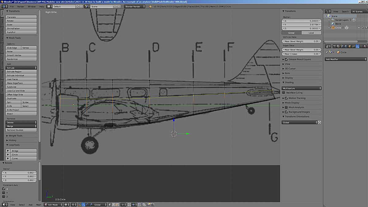
Side view
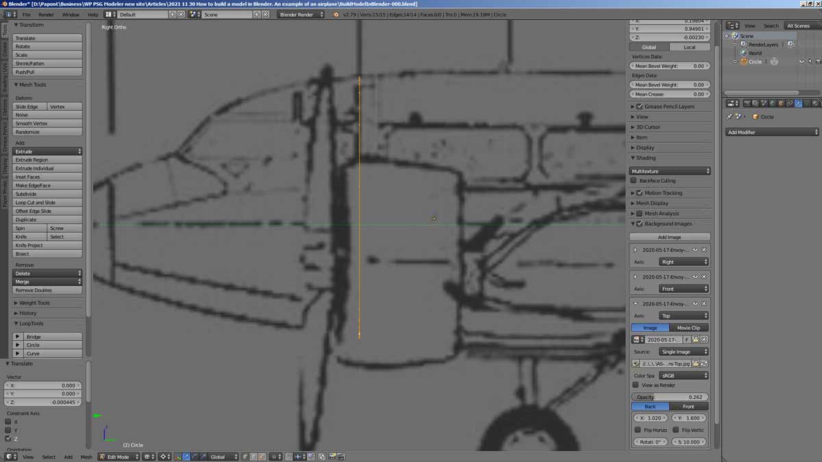
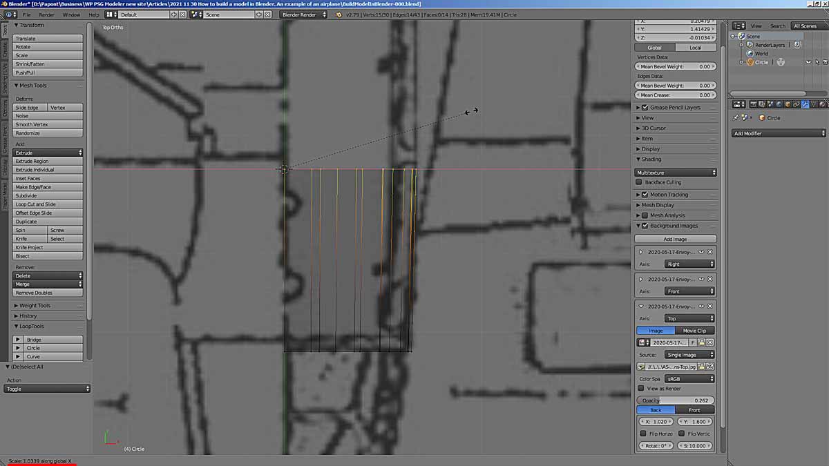
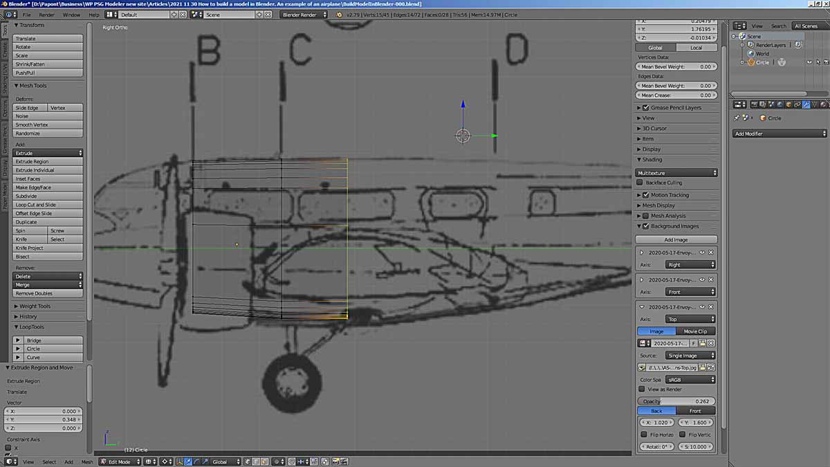
So far, so good. Now, using the Extrude command, extrude section B along the y-axis (you can press the Y key immediately after the E key) and place it in the place of section C.
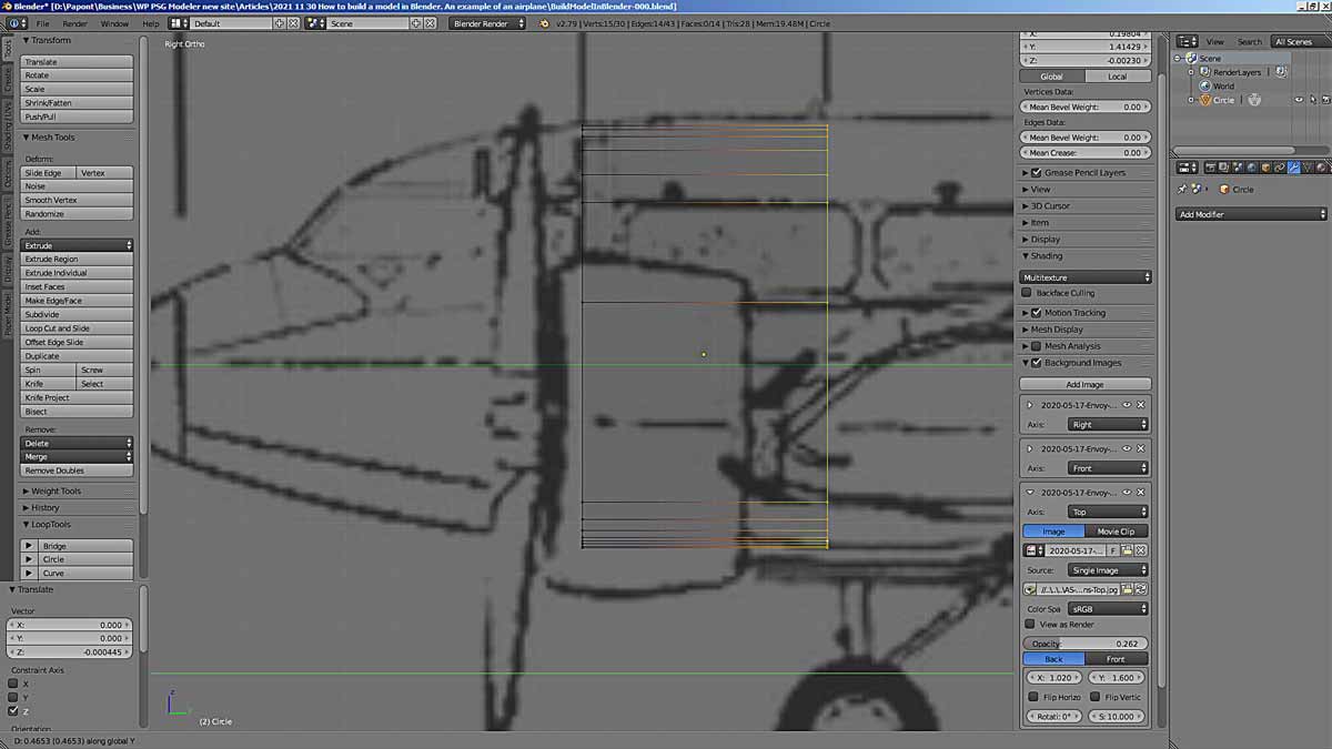
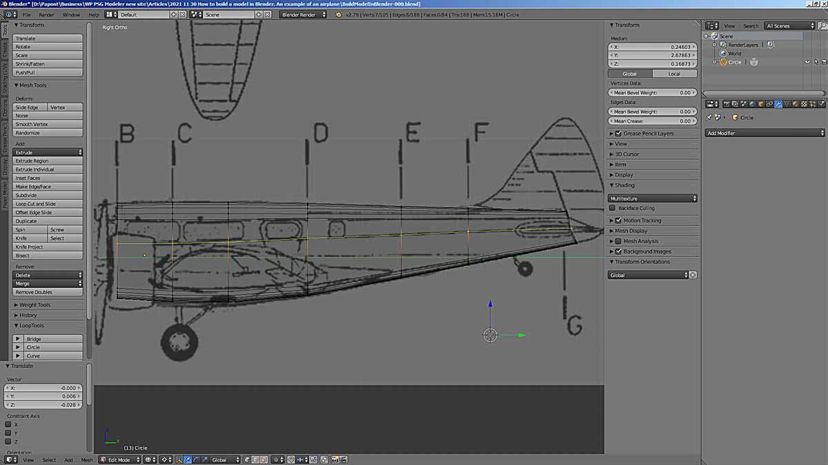
We extruded it out to the place of frame C. Now we need to form frame C. It should be higher and wider in accordance with the shape of the fuselage.
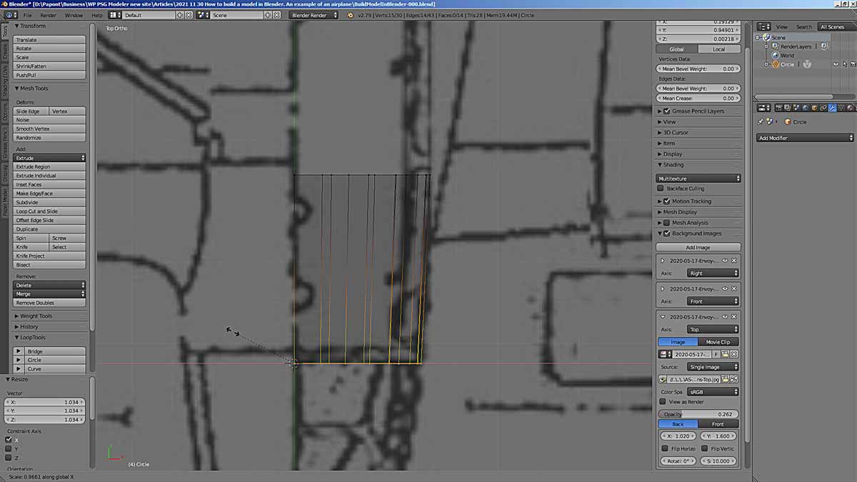
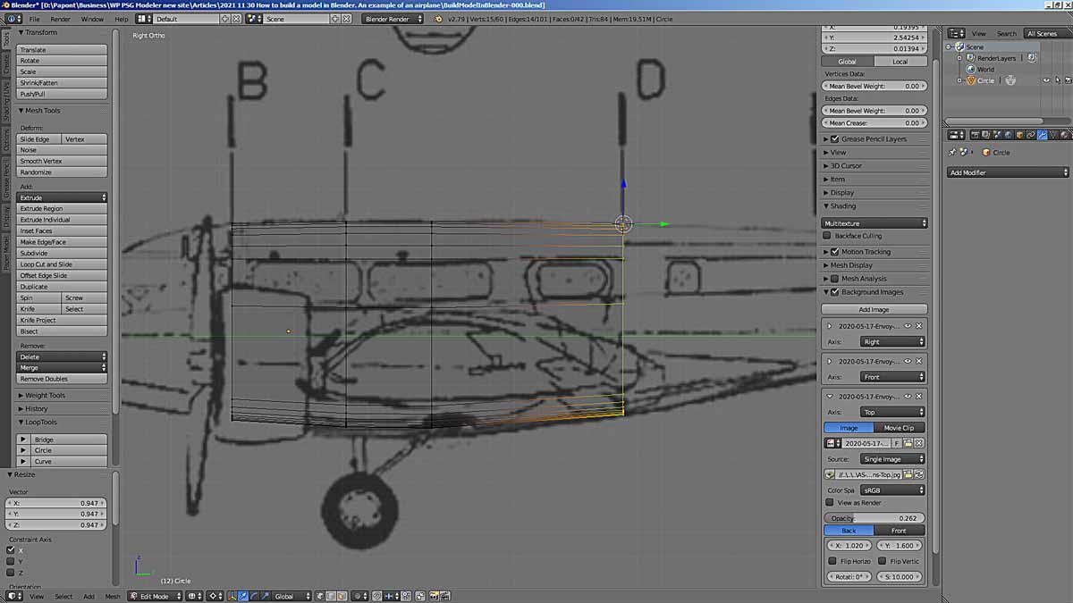
Let’s manipulate section C. Select it and increase it in height and width. We will increase by proportional scaling. First along the Z-axis, then along the X-axis, that is, in width. To do this, use the S command, indicating the axis we need.
If necessary, we correct the size and position of the sections.
Now let’s correct the width of section C.
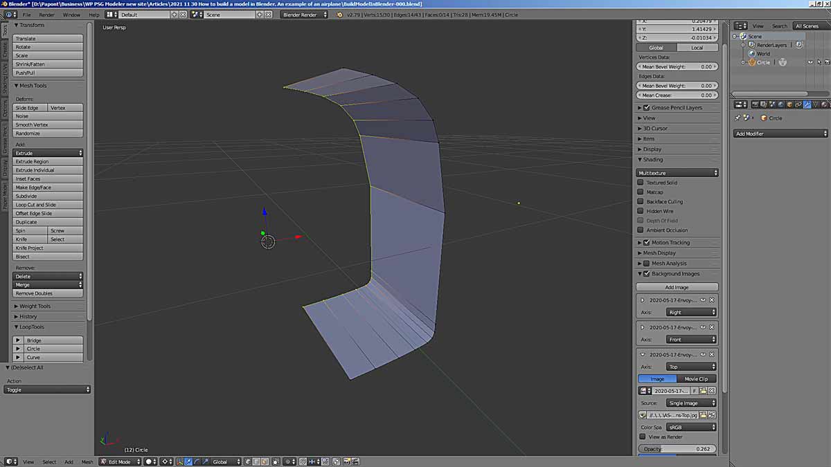
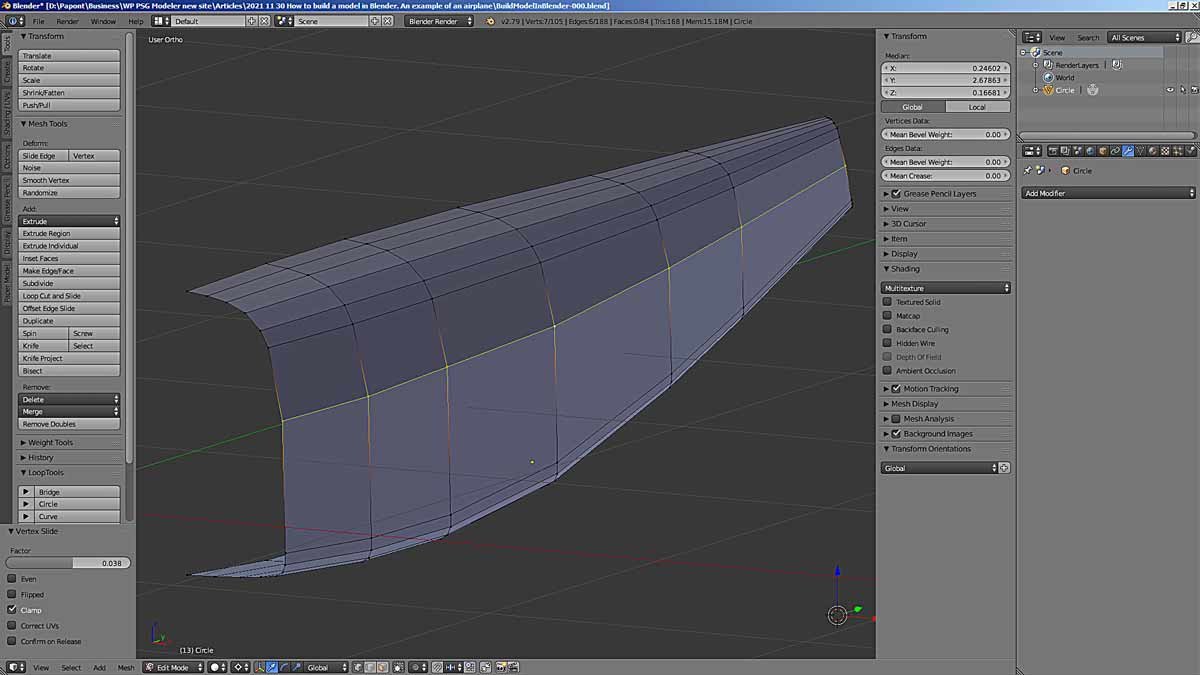
Here’s what we got.
It worked out well. Do not be confused by the edges and facets on the bottom rounding of the section. Taking into account the absolute size of this fuselage section and paper thickness, the error in the transition to the rounded shape will be negligible and can be neglected.
Now we need to see where to place the next frame of our 3D model. The next D section is in the picture too far. If you extrude out section C and put it in section D place, the shape of the fuselage will be very rough. It can be seen that it is necessary to make an intermediate frame of the C/D.
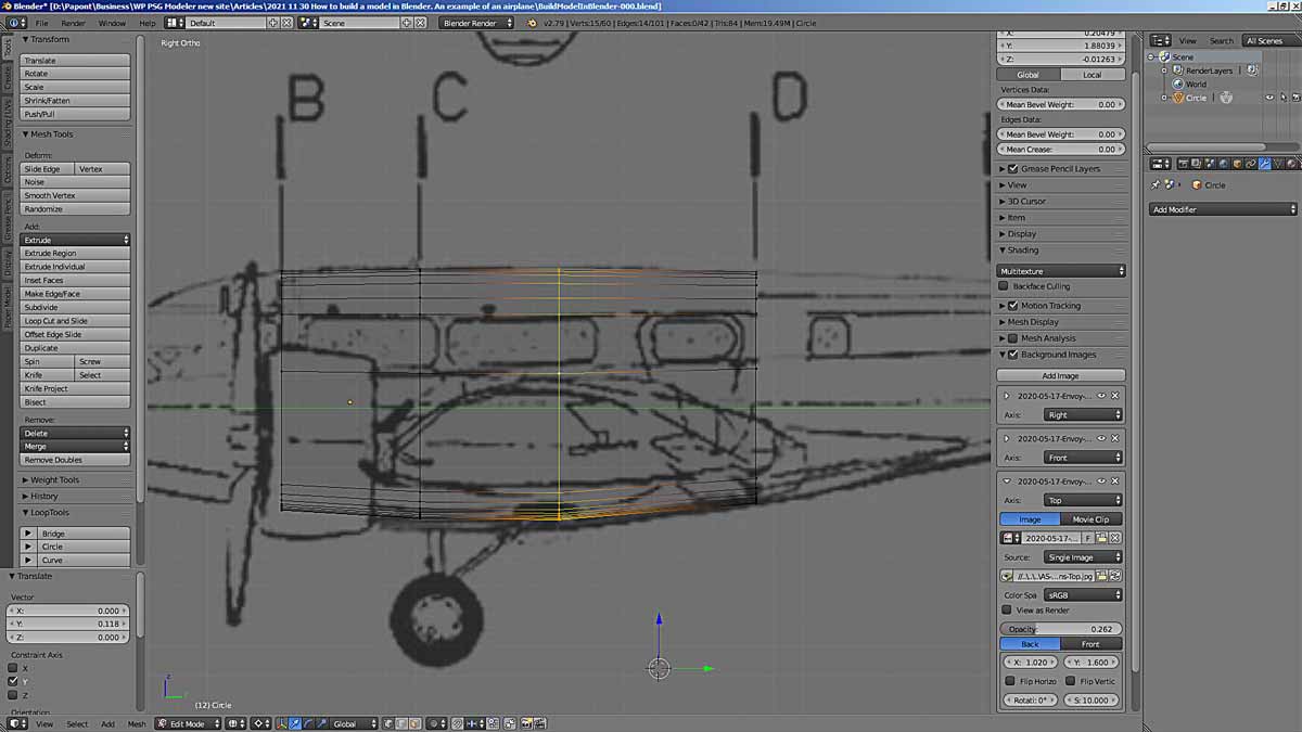
But where to put it along the length of the fuselage? If we look at the contour of the lower part of the fuselage, it becomes clear that the intermediate frame C/D should be placed at the inflection point of the contour of the lower part of the fuselage. We will extend the section C to this place between C and D. We will extrude the section only along the Y-axis.
Apply the Extrude command and select the y-axis by pressing the y key.
Now we need to bring the resulting section in line with the dimensions of the fuselage in height and width, just as we did in the previous modeling step. The edit is quite minor.
Now we move to section D. Just as we have done so far. We immediately correct the shape of the section in height and width. Here’s what we have.
In the picture, we see that the intermediate C/D section should be shifted back towards the fuselage tail. This will improve the division of the fuselage into sections, but will distort the shape of the lower fuselage. I choose to move the section C/D.
This is the main disadvantage of this forming method. It is not always possible to accurately represent the shape of the modeled object. I do not exclude this method completely, but only say that it is worth using it only in strictly defined cases. For example, running far ahead, I can say that by this method I will make the roof of the fuselage on this model.
Let’s finish making the fuselage. The sequence of actions is repeated.
The last section of the fuselage is inclined. It must be rotated using the Rotate (R) command.
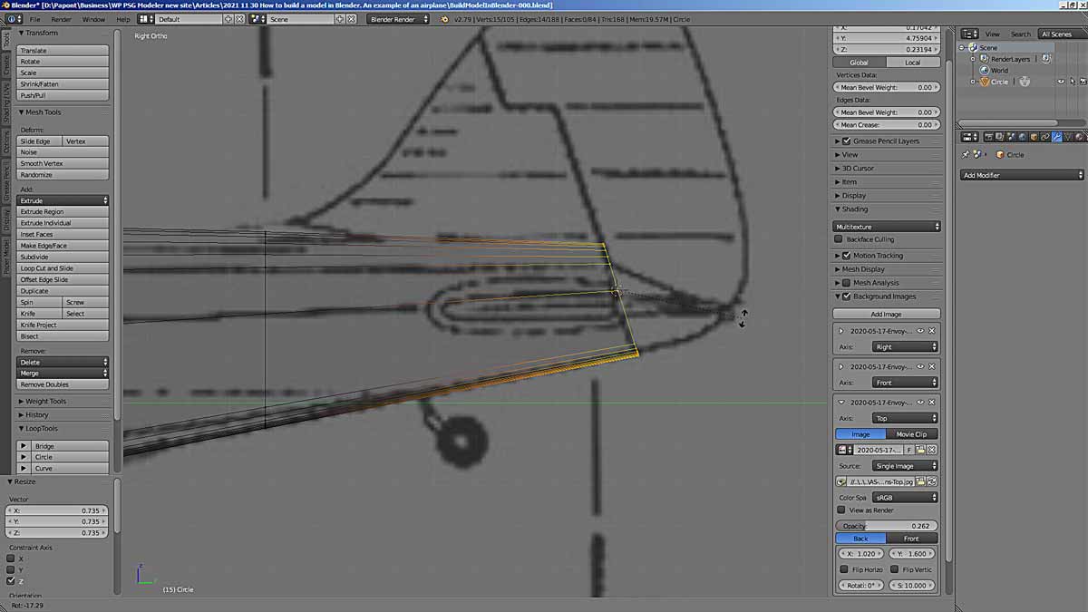
Now let’s take a closer look at what we got. The first thing that catches your eye is the inaccurate lines of the joints of the flat board panel with illuminators. In the side view, the lines of the upper and lower edges of the panel with illuminators should be corrected in accordance with the drawing. Especially the bottom line.
Let’s do it.
This is how we got the fuselage of the aircraft. While without a cockpit. There the form is complex, and it is better to consider it separately. Which is what I suggest you do next time.
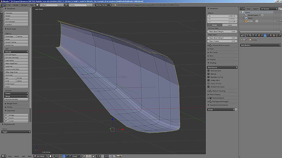
In the meantime, you can take a look along the fuselage and fix those curved lines that turned out badly. You should get something like this. Or better.
To be continue…