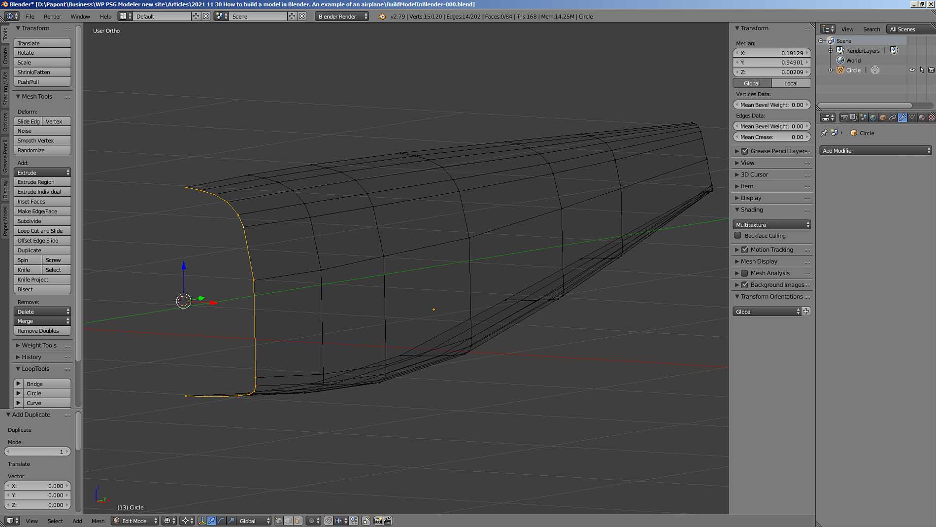
Let’s continue building the fuselage of our aircraft. Now we need to make the cockpit. At the beginning, we will hide the made part of the fuselage so that it does not interfere with us. To do this, copy the bow frame: command Ctrl D + Enter. The copied frame remains in place.
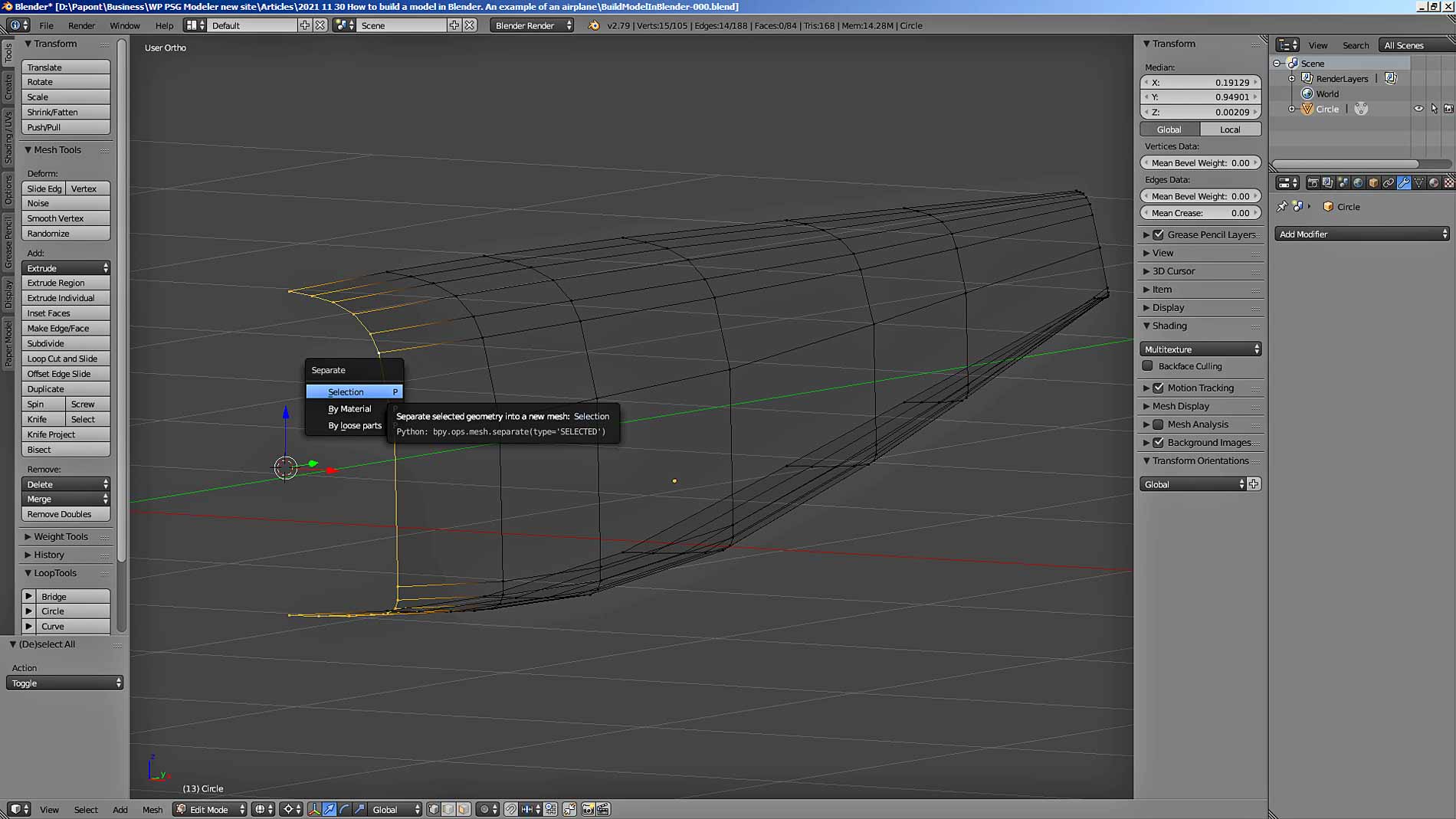
Then we will separate it from the fuselage so that it becomes a separate, independent part. This is done using the Separate – Selection – P command.
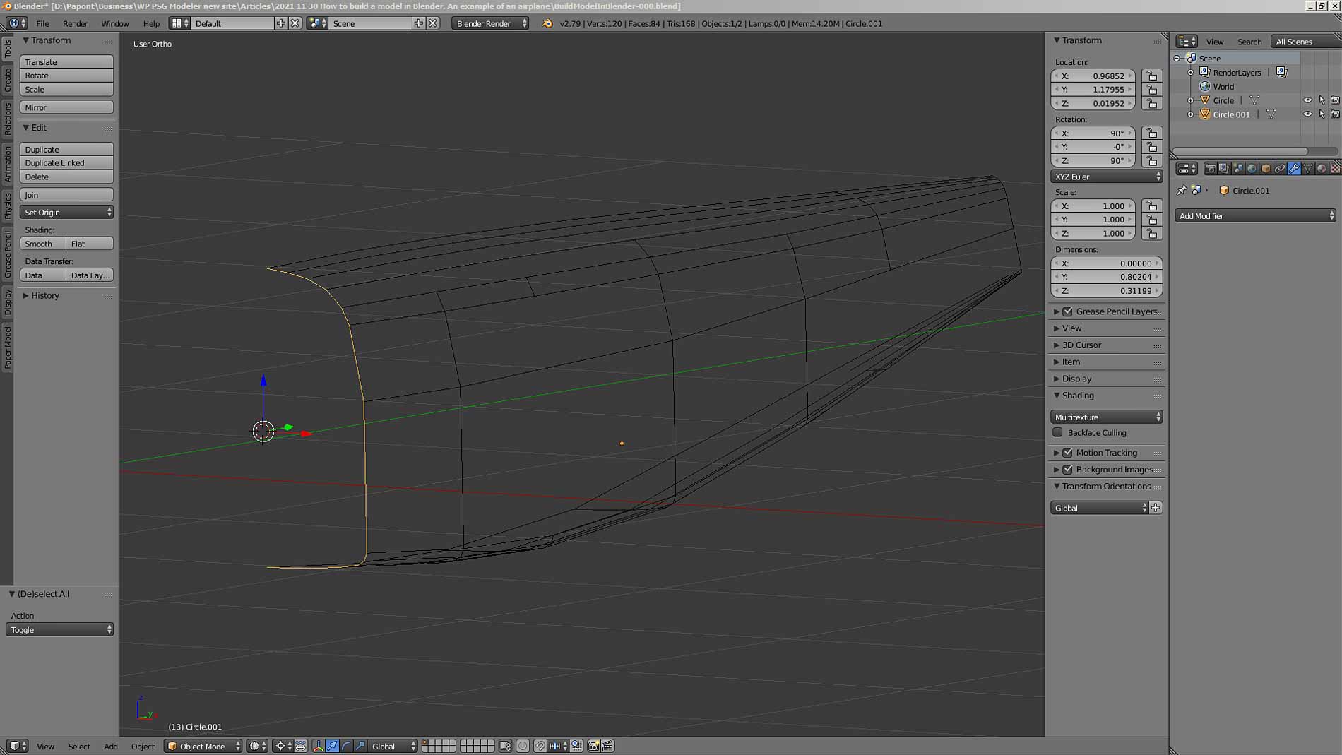
Let’s go back to Object Mode and deselect all objects. Then select the copied frame.
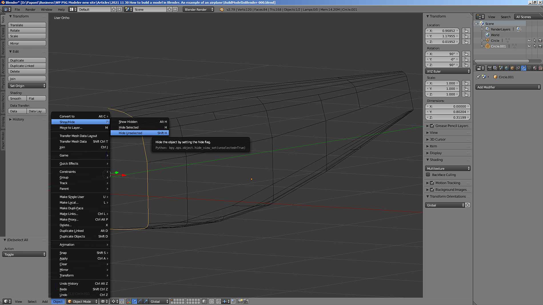
Now let’s hide the fuselage we don’t need now: the Shift H command.
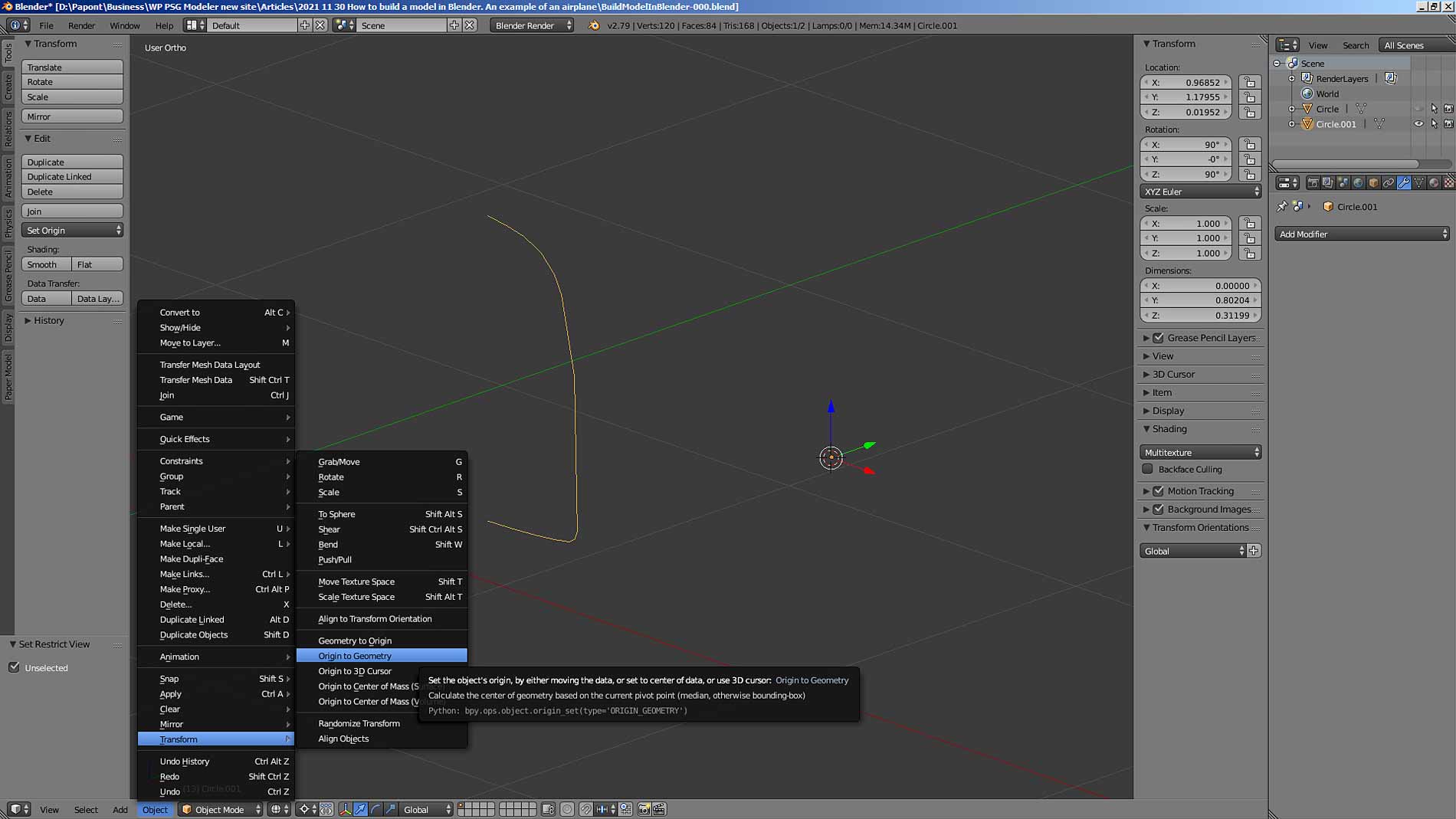
There is a frame on the Blender Main Window and a yellow dot on the right. This point is very important. This is the Origin or the main point of the object, relative to which all actions are performed on the object. For example, if you want to apply the Mirror modifier to an object, that is, to get a symmetrical object from the existing one, then the axis of symmetry will pass exactly through the Origin, through the main point of the object. In Blender, every single object has its own main Origin point.
We copied the frame and separated it from the made part of the fuselage. Therefore, our frame inherited the position of the main Origin point of the entire fuselage. This point is visible in all the previous pictures. To get the transformations we need with our frame, we need to put its main Origin point in the characteristic place of the object. This is usually the center of symmetry of the object. This is done in Object Mode by the special command Object – Transform – Origin To Geometry. The coordinates of the objects are determined relative to the Origin of the main point of the object.
Please note that it is often necessary to place an object in a precisely defined place. For example, on the coordinate axis. To accurately position the object, you can first place the 3D cursor in the desired place, which has its own panel where you can enter its coordinates.
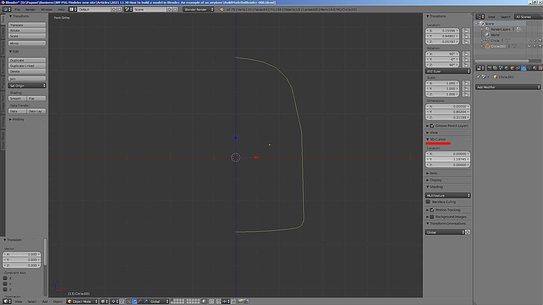
Then you need to move the main point Origin to the point at which the 3D cursor is located. To do this, in Object Mode, select the command Object – Transform – Origin To 3D Cursor …
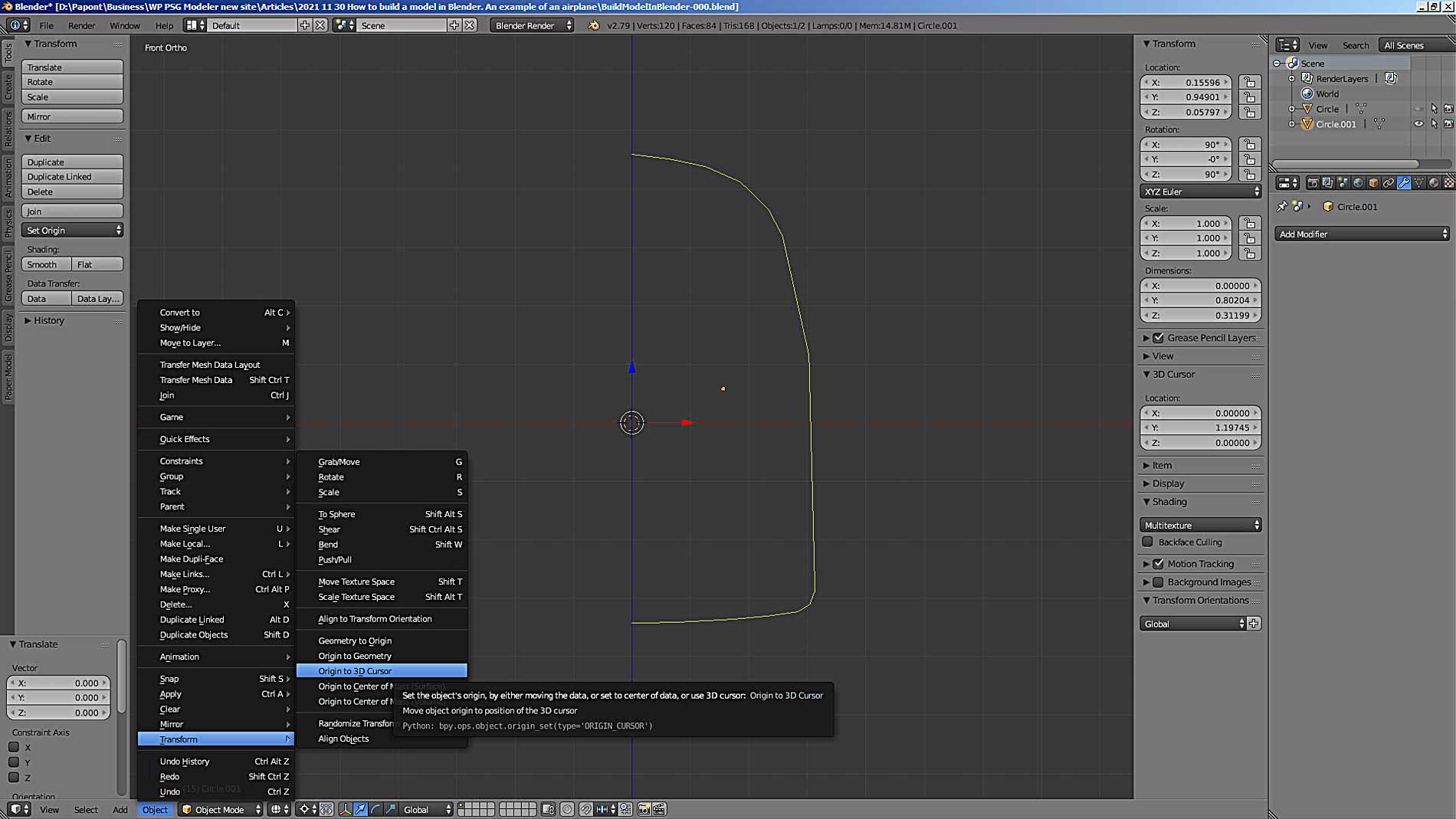
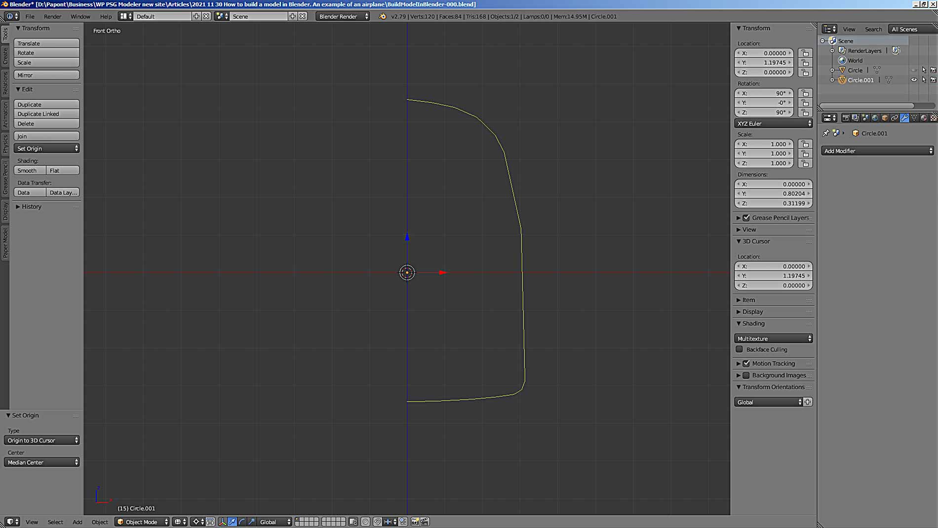
… and get the desired position of the Origin point. In our case, it is located on the z-axis, which gives us the opportunity, if necessary, to add the second half of the frame using the Mirror command.
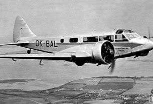
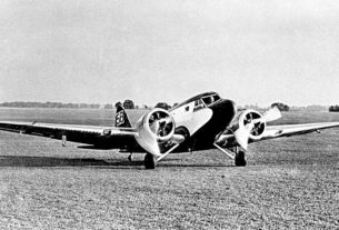
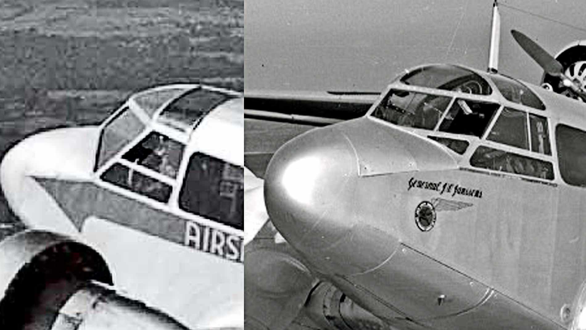
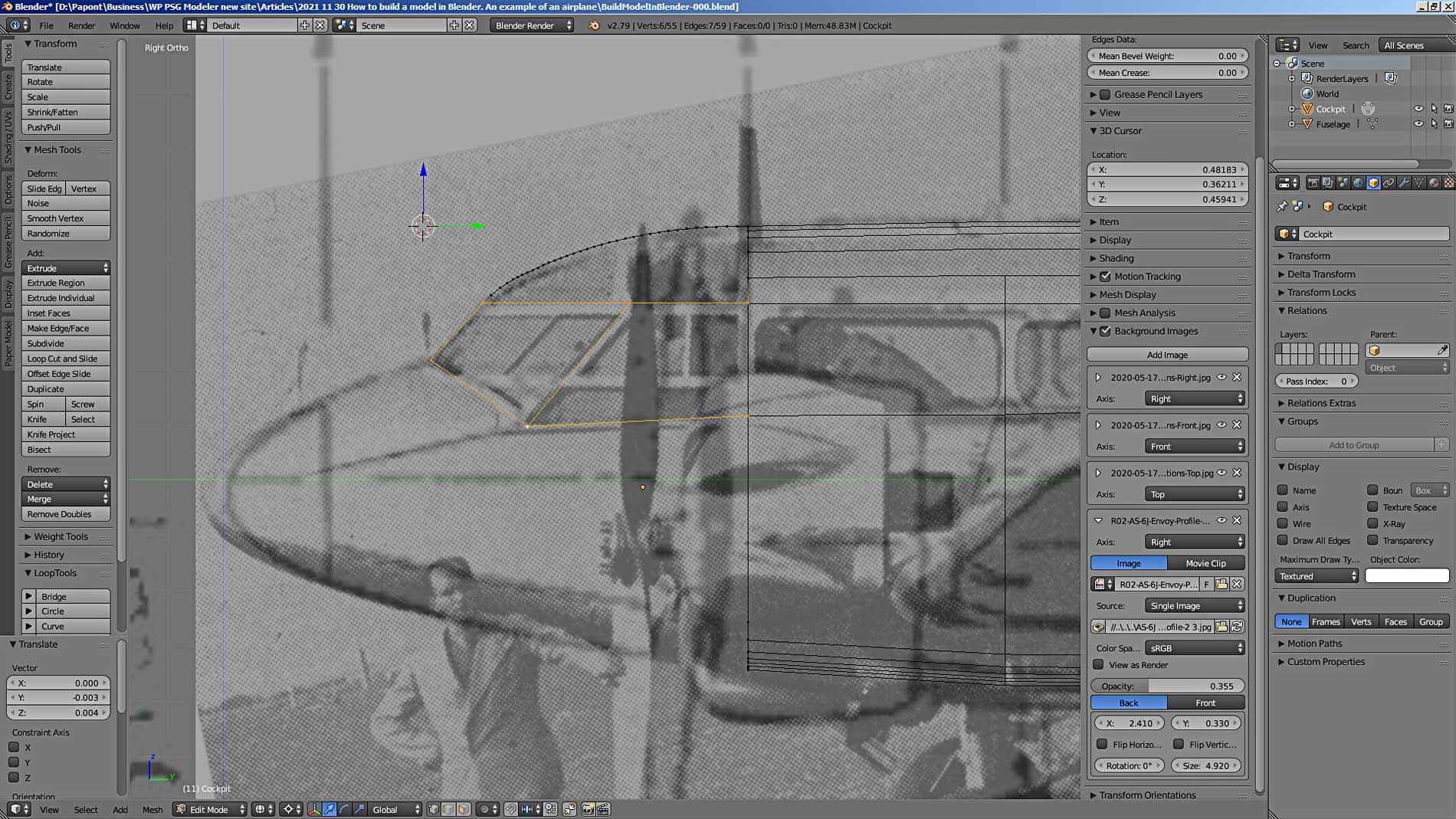
Now, as in the case of the tail section of the fuselage, we will need to extrude the resulting frame. Now towards the nose. However, the shape of the nose of the fuselage is more complicated. To understand its shape, you need to look at the photographs of the plane.
The photo shows that the front glass of the cockpit is like a wedge. On top of the cab are two glazed panels: the front one looks like a half of a cone with its apex, the back part looks like the side surface of a truncated cone.
Having understood these shapes, you first need to build the side contour of the cockpit. It is more convenient and faster to do this using a curve. Let’s add a NURBS curve. I like it more than the Bézier curve. Let’s execute the Add – Curve – Nurbs curve command, having previously placed the 3D cursor in the place where we want to get a new object – our NURBS curve.
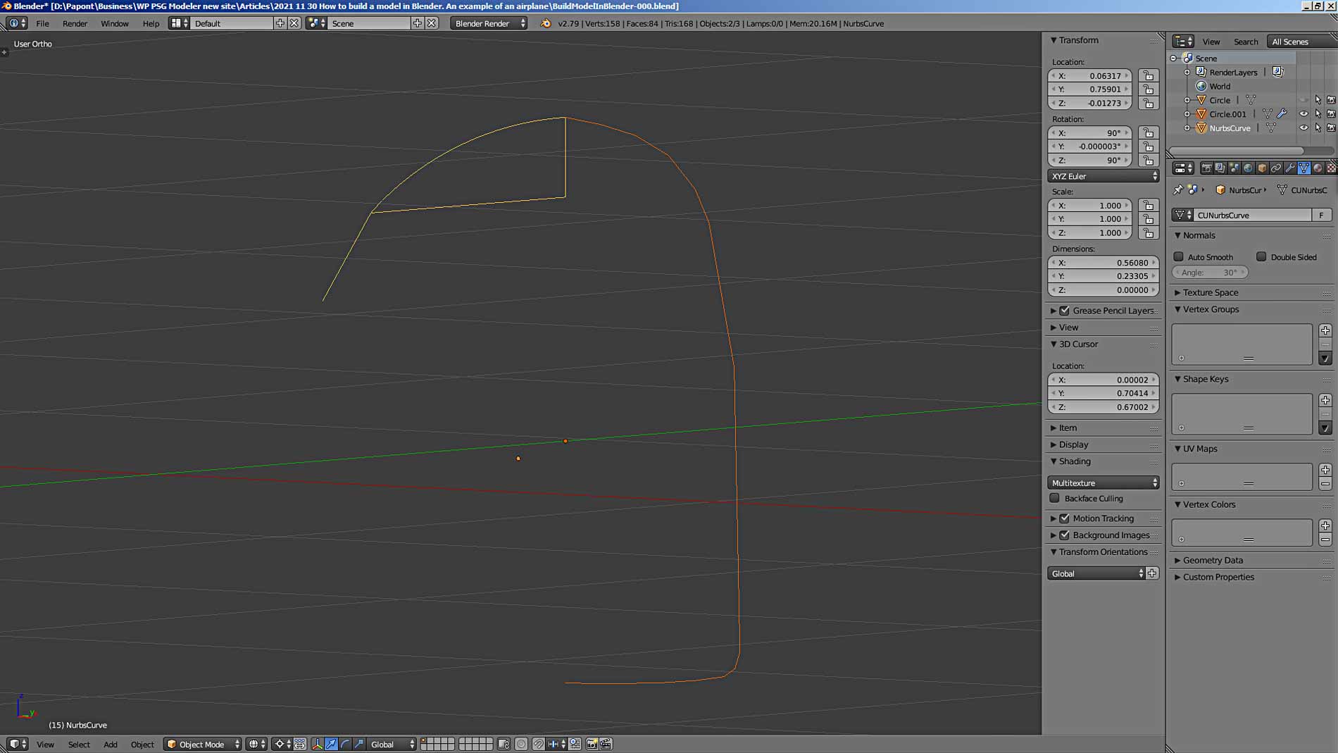
The curve appears in the horizontal XY plane, so it will have to be rotated to the desired YZ plane using the Rotate (R) command. Here’s what you should get.
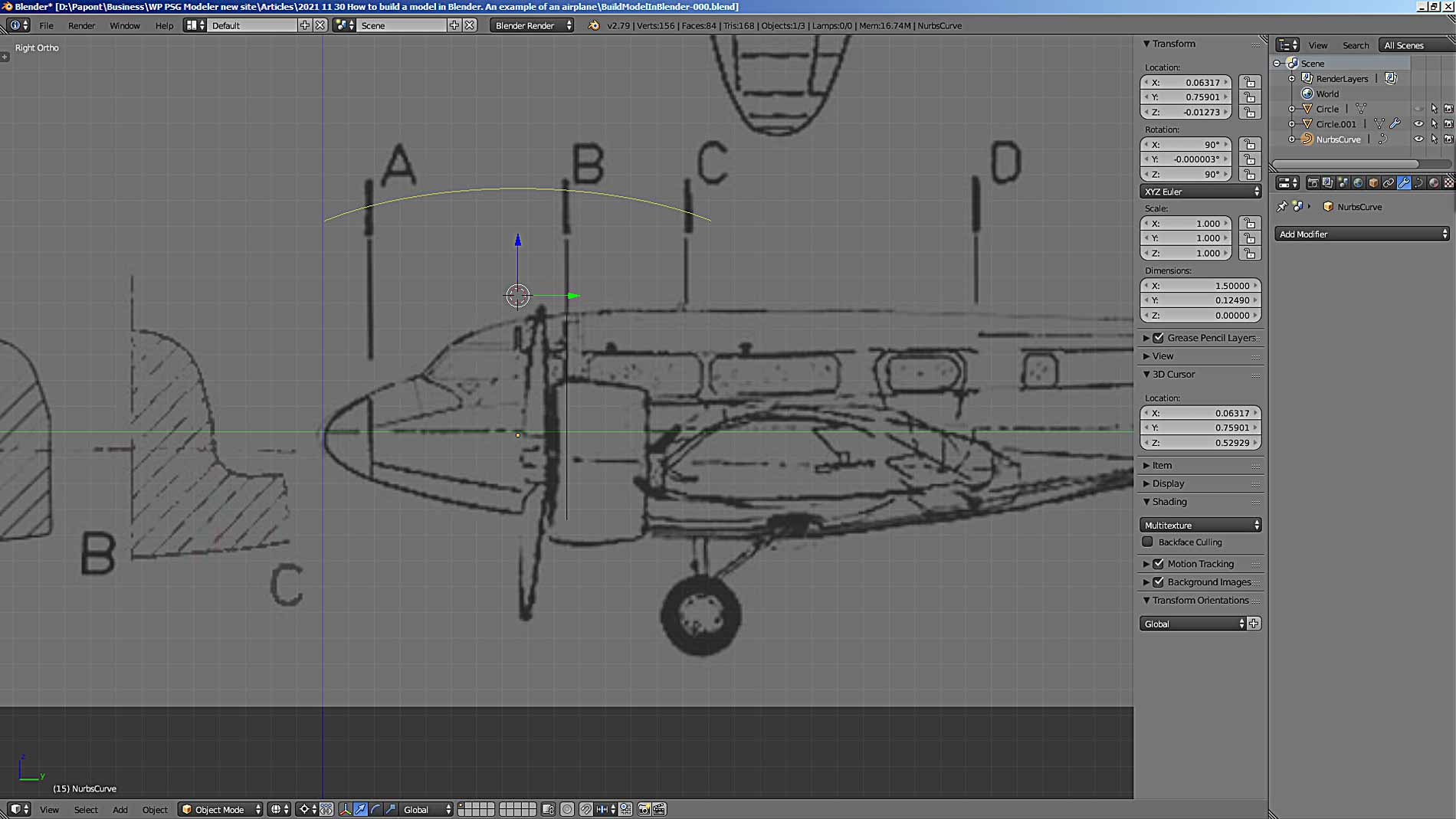
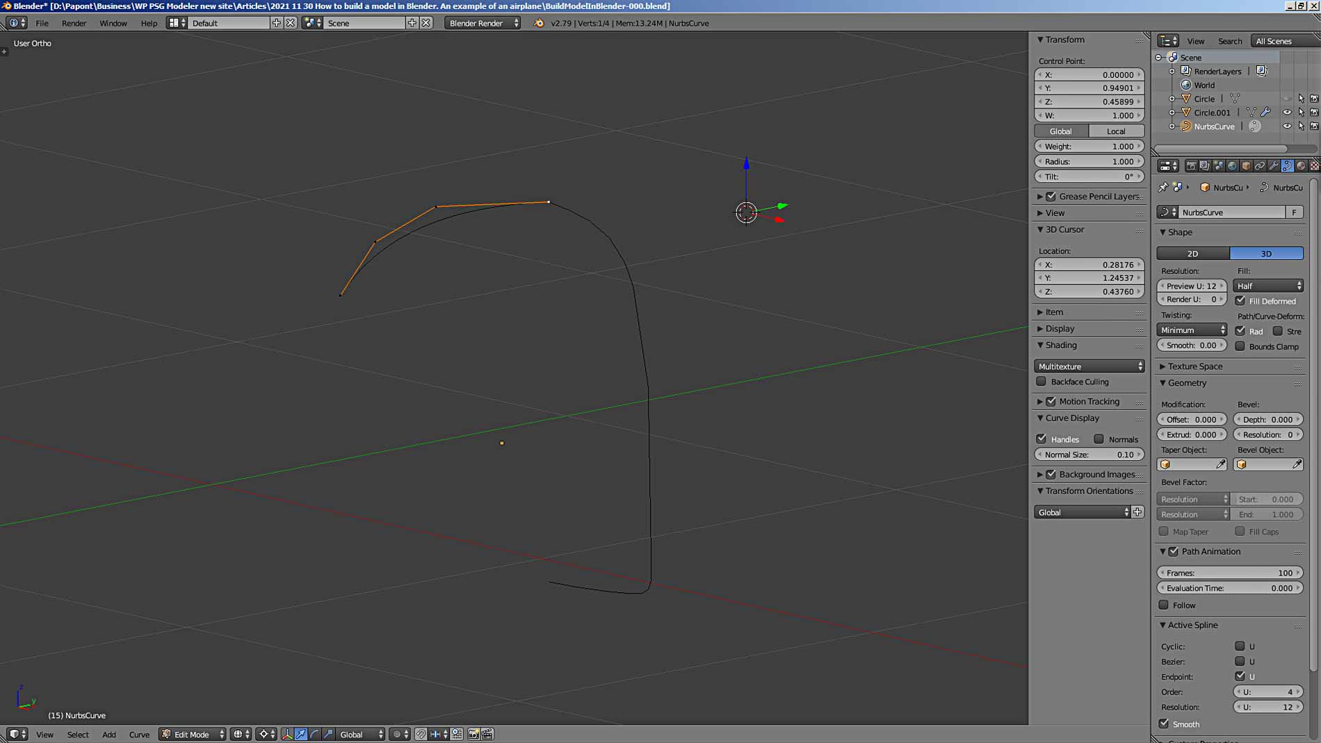
Let’s go to Edit Mode. We will see a terrible picture.
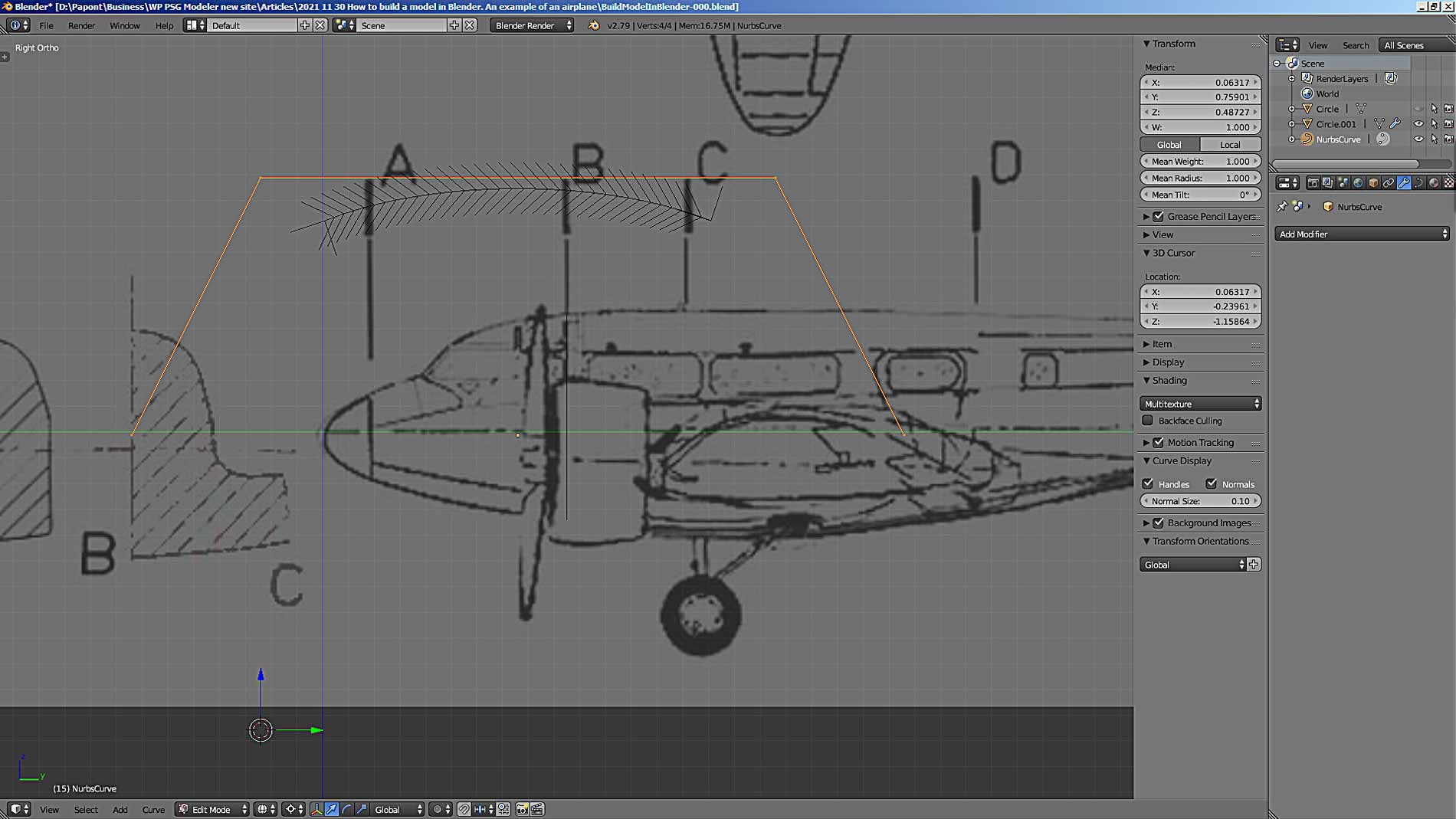
First, instead of a curve, there is some kind of “strange hairy caterpillar”. And secondly, this “caterpillar” lacks a front segment and a rear one. What the developers of the program had in mind is not clear to me. But, I prefer to get rid of the “hairiness” and give the curve a normal look.
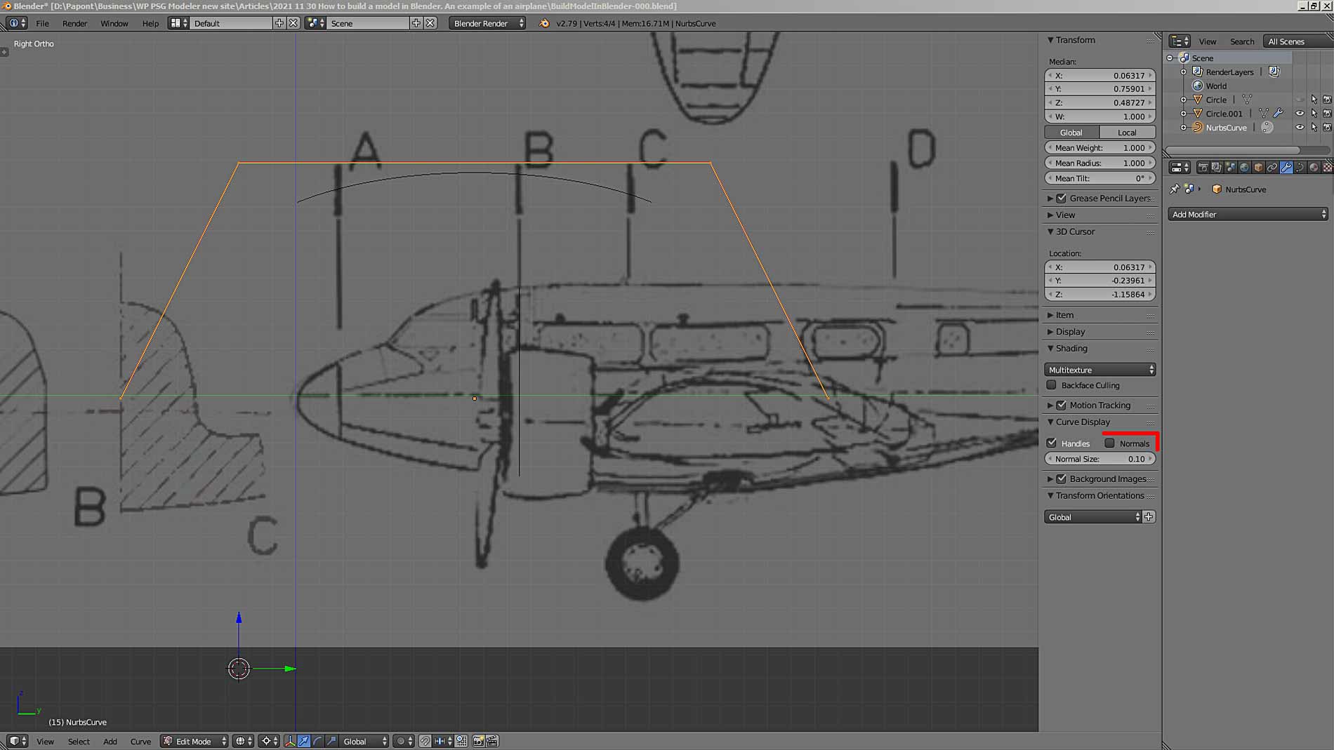
The first drawback is removed simply. It is necessary to open the Curve Display panel, which is located in the right tab of the main program window and is opened with the N key. In this panel, find the Normals checkbox and uncheck the box there. After that, our curve will lose its “hairiness” and become a “normal” curve.
Now we need to find the Properties editor panel. It is located on the right side of the edge of your monitor screen. Here, on the contrary, you need to put a tick in the checkbox on the Active Spline panel, the Endpoint parameter.
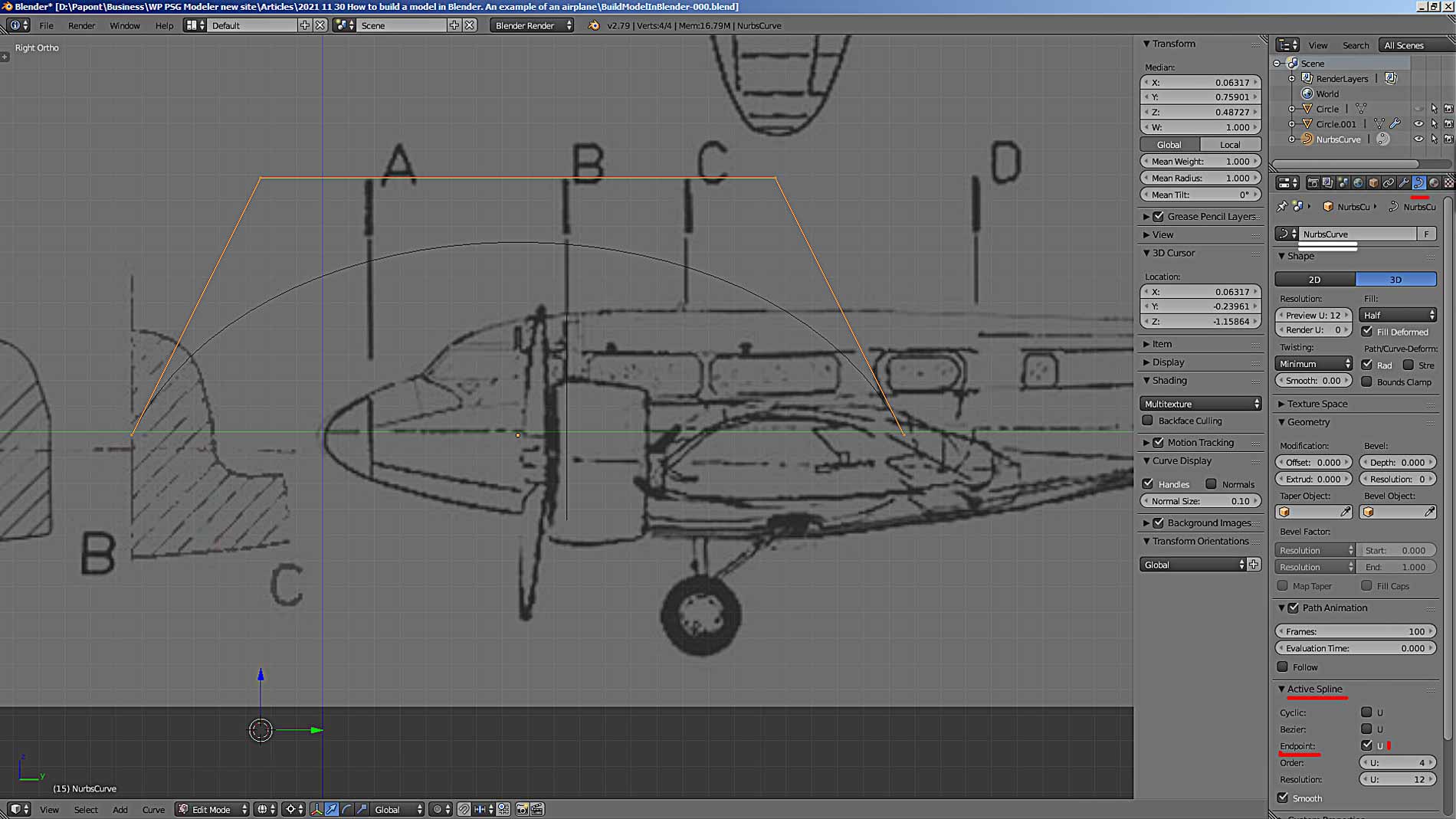
By the way, it would be very nice to get into the habit of immediately naming new objects. There are good opportunities for this in Blender. The picture above shows a window where you can enter a name for our curve. I marked it with two white stripes.
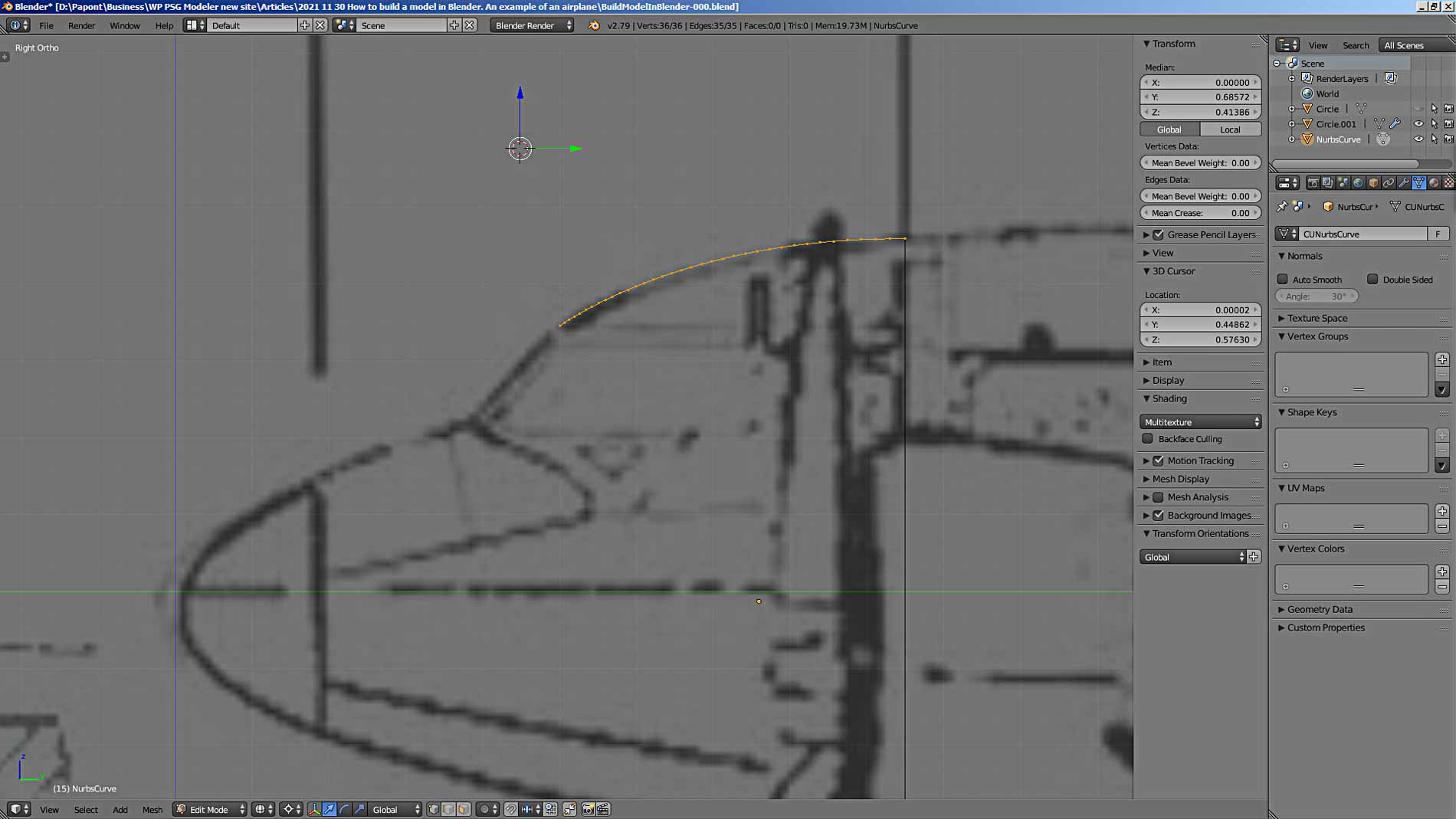
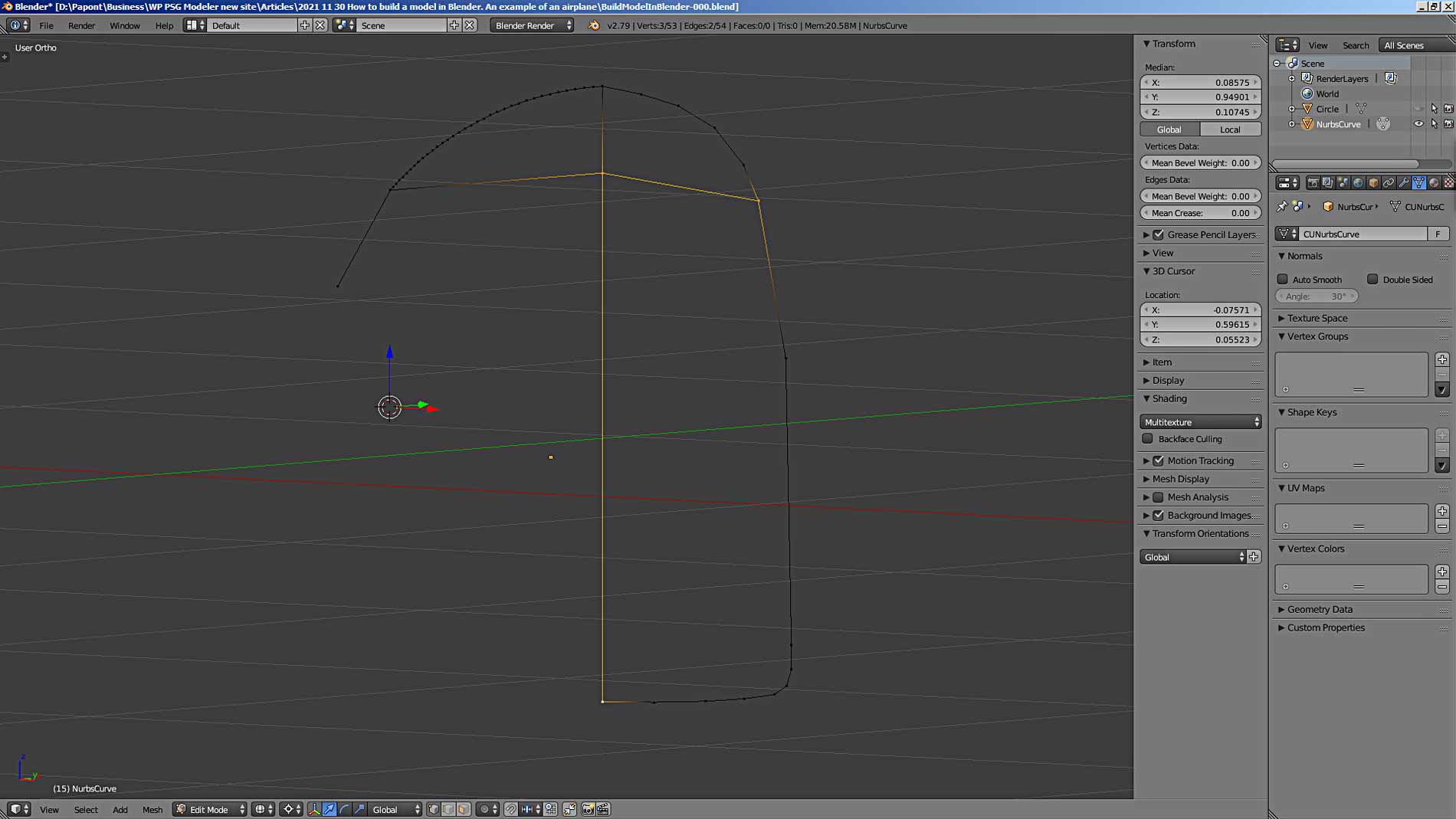
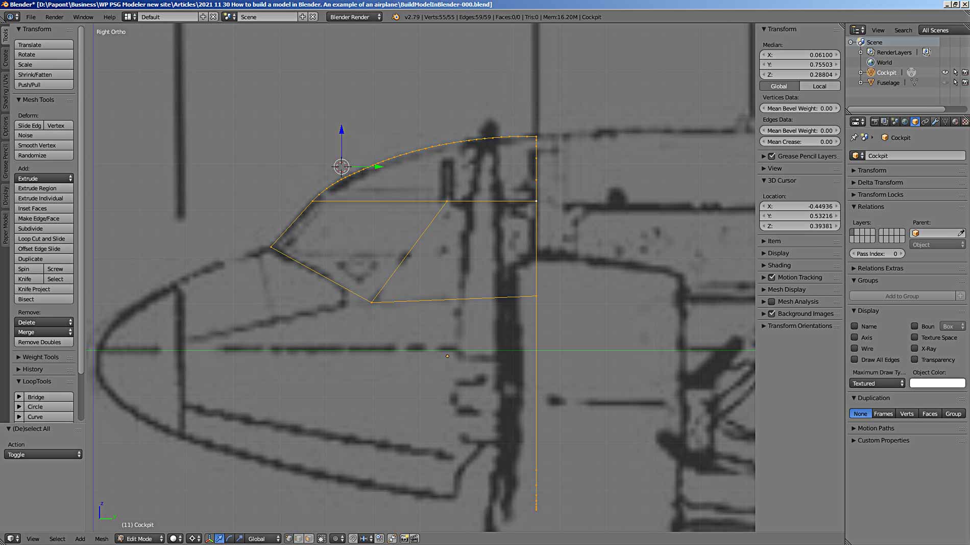
Now we have everything we need to accurately repeat the contour of the fuselage of our aircraft. The Nurbs curve has four vertices connected by a yellow broken line. These vertices allow you to shape the curve in any desired shape. Let’s repeat the curved contour of the cockpit roof.
Let’s start with the right control vertex. We know the exact place where this vertex should be located. This is the upper point of the frame, lying in the center plane of the fuselage. That is, the X-coordinate of this point will be zero. We can get the other two coordinates by looking at the coordinates of the upper point of the frame.
Select the top point of the frame and put its coordinates in the 3D cursor window. Thus, the 3D cursor will move to the top point of the frame. Now let’s move the coordinates of the 3D cursor to the windows for the coordinates of the right control point of the Nurbs curve. She will take the position we need.
I think there should be a special command to automatically assign the coordinates of the desired 3D point to the cursor or another point that needs to be placed in a certain place. But, I have not found such a command yet. I can explain the absence of such an important and convenient command only by the fact that Blender is focused primarily on modeling artistic rather than technical objects.
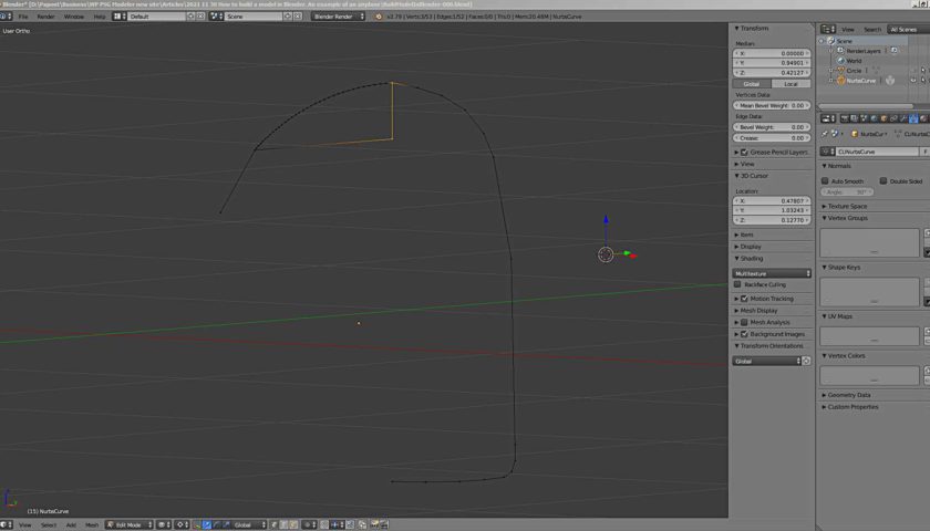
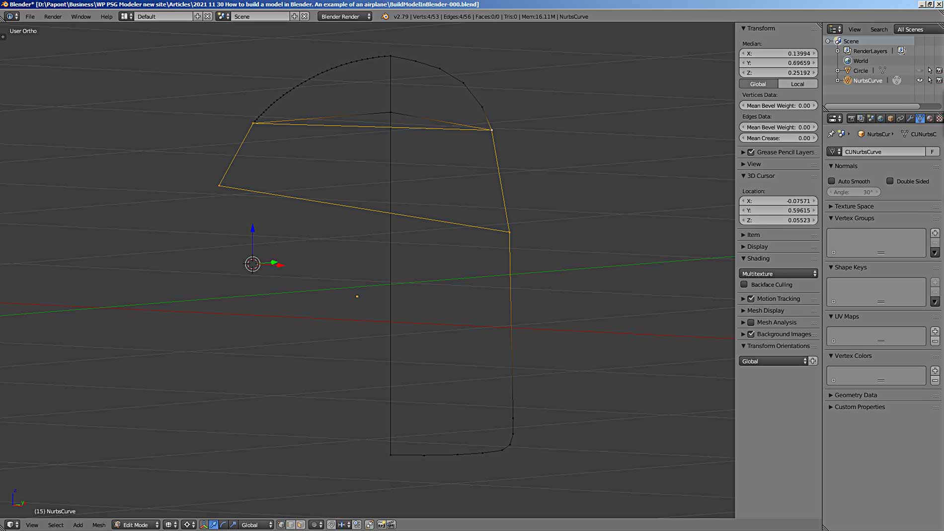
Now we will place the remaining three control points of our curve so that the curve exactly follows the contour of the cockpit roof.
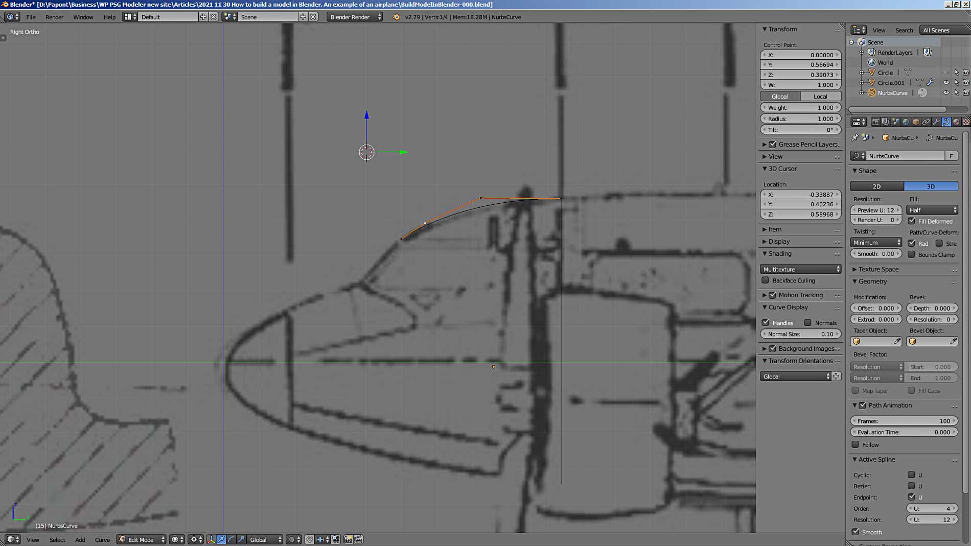
Since the picture of the airplane is very rough, this gives us more freedom to “draw” our model. Here’s what you should get. This curve suits me perfectly.
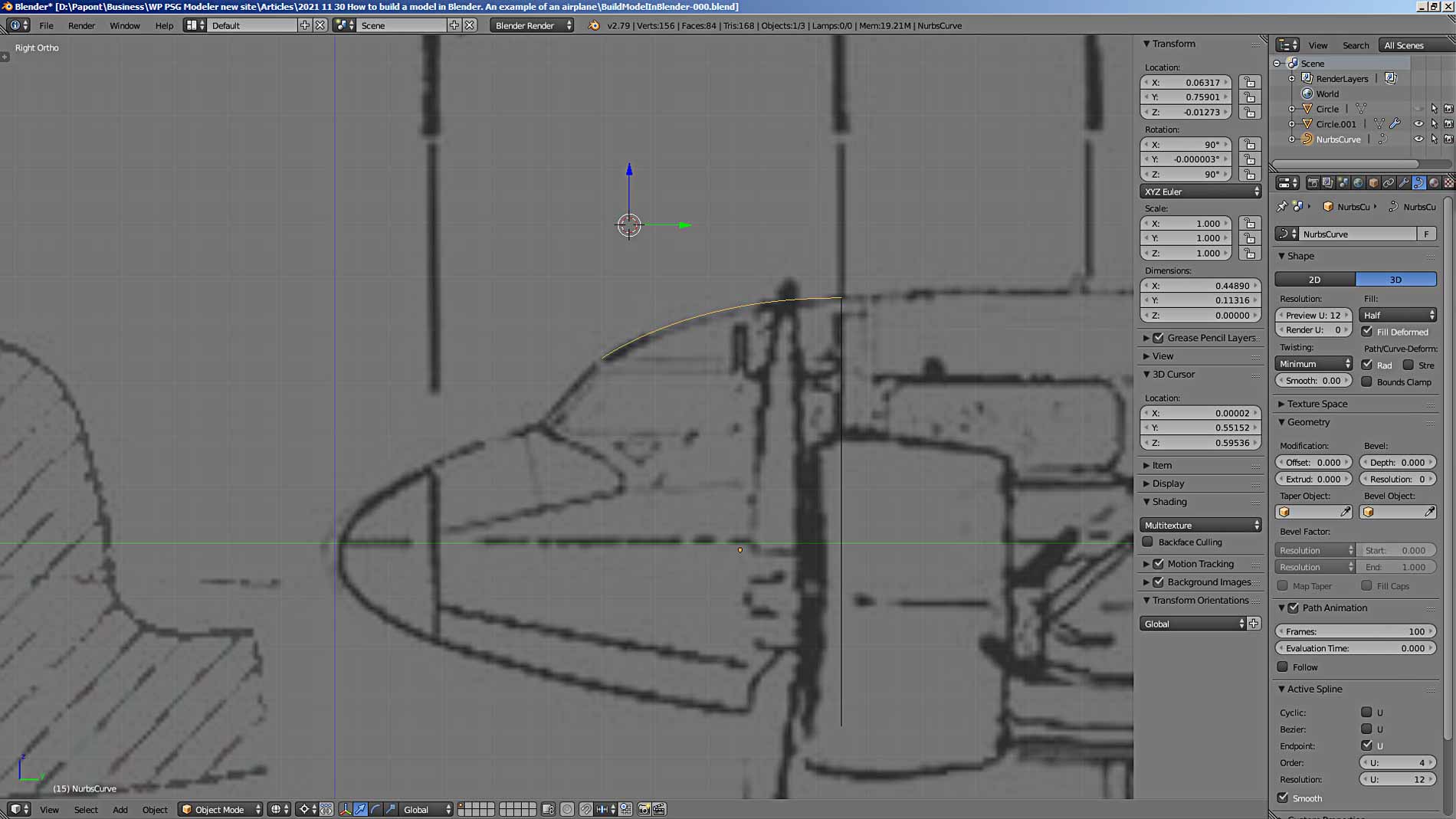
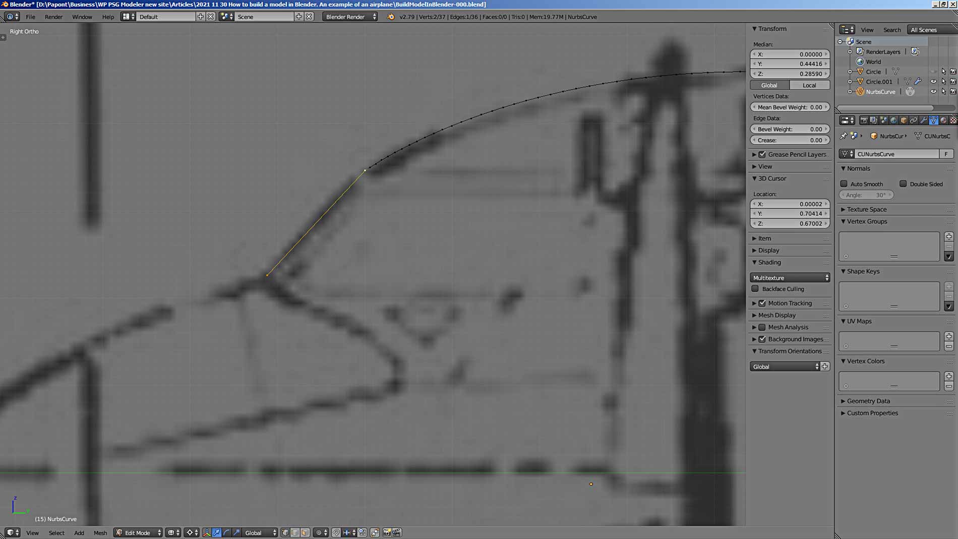
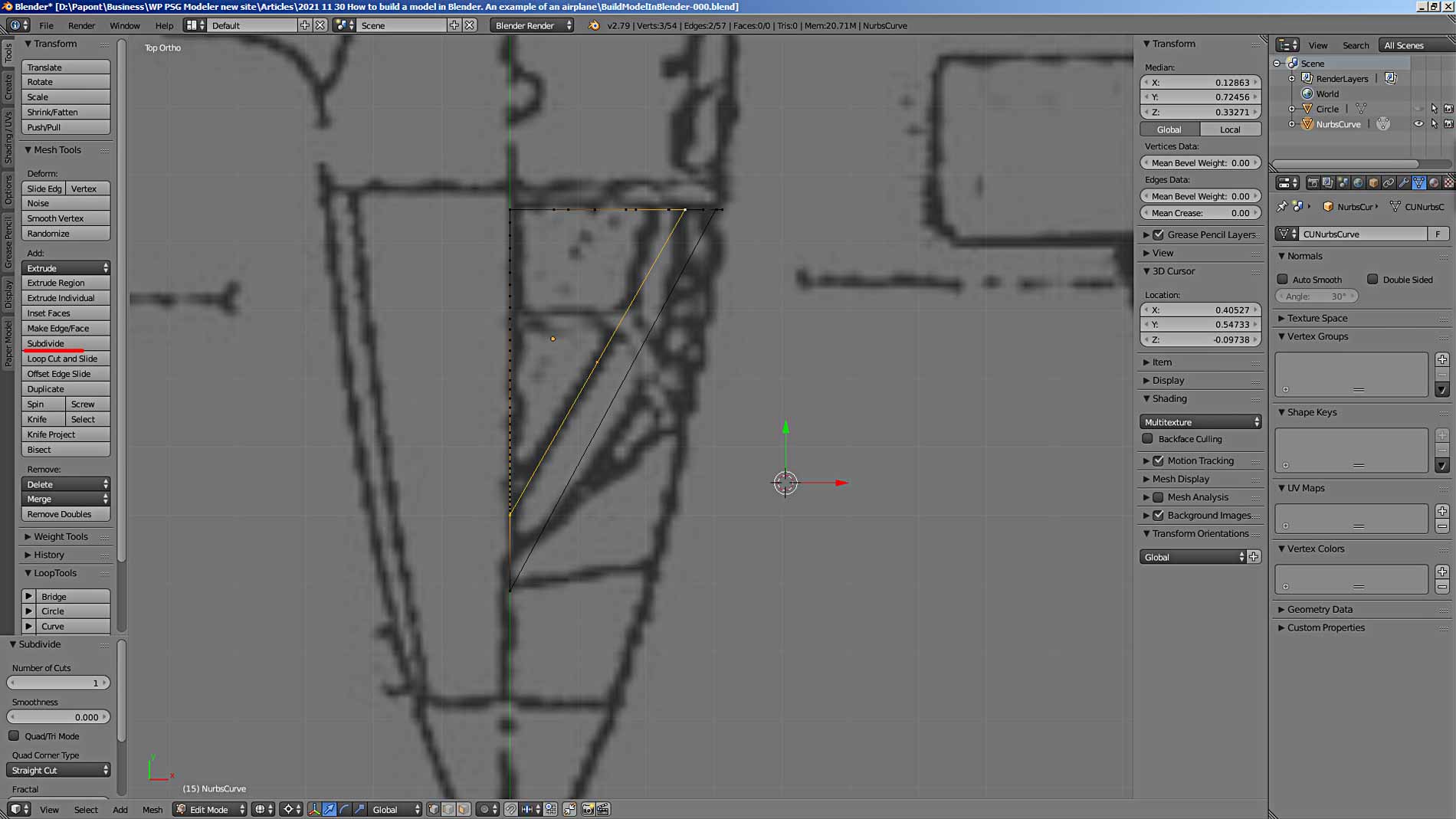
Further, the contour of the cockpit turns into a straight line that runs along the forward edge of the pillar holding the cockpit glazing. This means that we need to draw a straight line. However, here we run into a problem. You can not “attach” a straight line to the curve line. For this case and for similar others, there is a command in Blender that can convert a curve to a mesh and vice versa. That is, curve to mesh and mesh to curve.
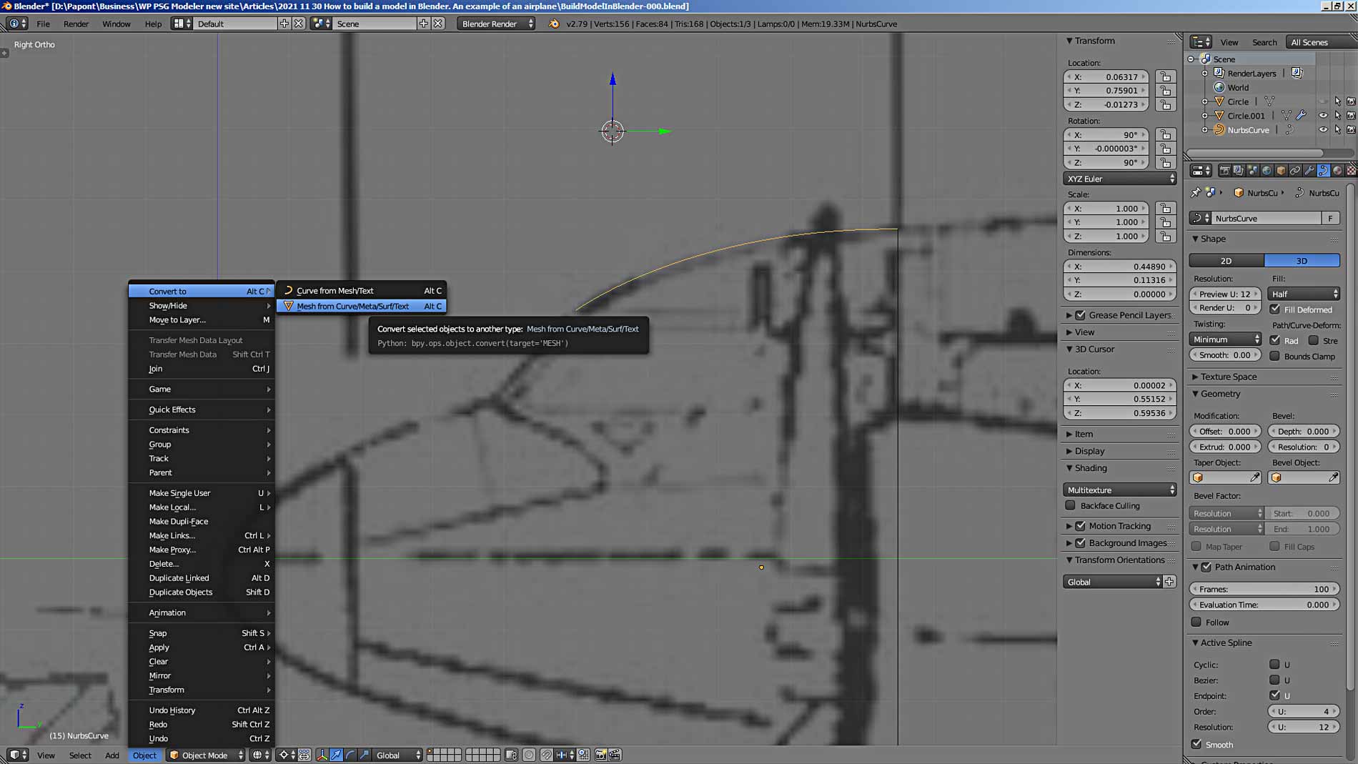
Select our Nurbs curve in Object Mode. Let’s execute the command Object – Convert to – Mesh from Curve / Meta / Surf / Text or easier – Alt C. Our curve will turn into a mesh, that is, into a set of vertices.
Let’s see what we got. Quite a decent curve, that is, a broken line. If there are a lot of points, then you can remove the extra ones. Usually I do this later, when the main thing has already been done, the object is modeled, and you can do a little optimization.
We must be careful here, because the mesh we obtained from the curve is no longer a smooth curve, but a broken line (poly line) consisting of rectilinear segments. It is clear that the more we remove the points, the coarser our curved cockpit contour line will be represented by the mesh. Here, you need to focus on the scale of the model and the absolute size of the modeled objects.
Now the left point of the resulting mesh can be extruded with the Extrude command and get a straight line.
Now we need to draw an auxiliary line that will run in the center plane of the fuselage. This line will later help us build the rear of the cockpit. Extrude the upper vertex of the cockpit glazing stiffening plate into a straight line. We need to bring this top to the place occupied by the frame. The coordinate of the frame is known. The same value must be given to the point coordinate.
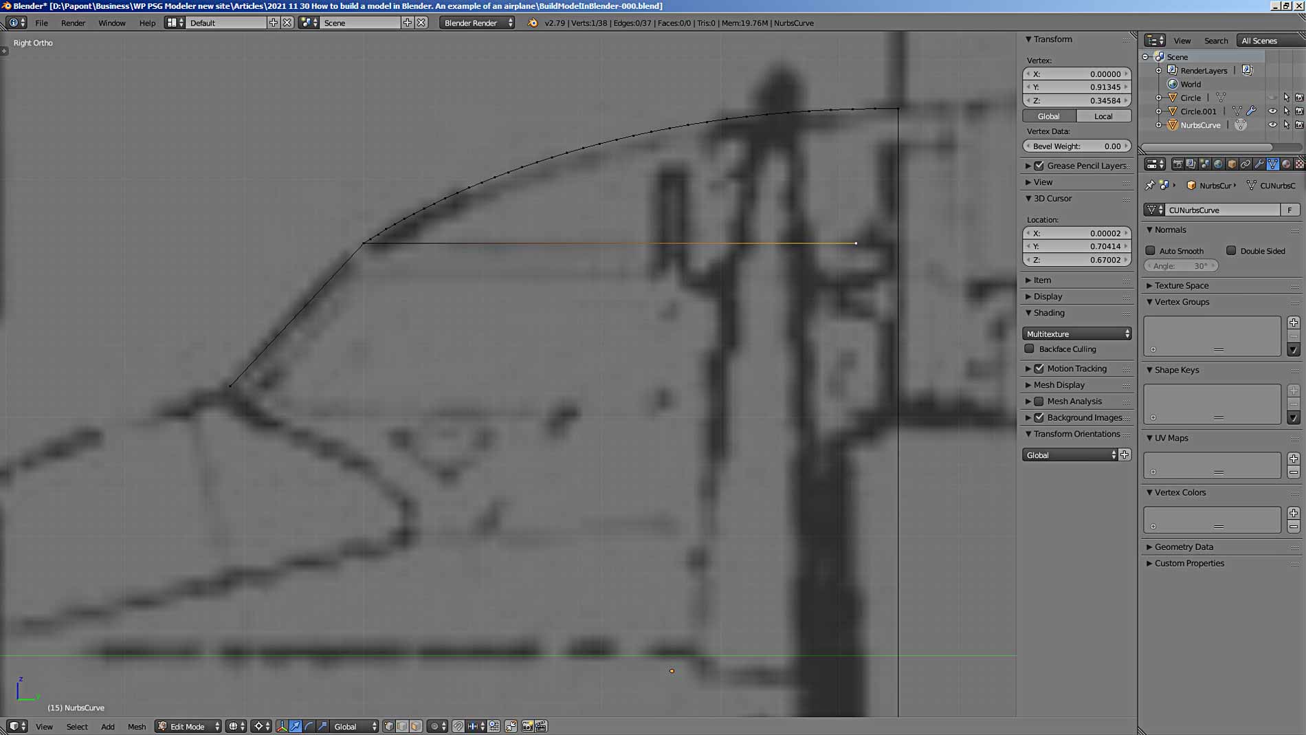
It turned out like this. The top point in the picture has the same Y-coordinate as the frame. We take its value and substitute it in the coordinate at the extruded point.
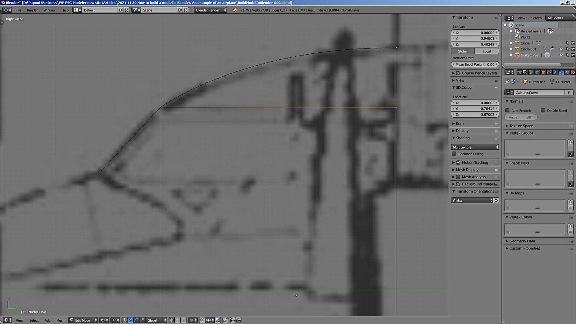
To connect two points with an edge, you need to select them and press the F key. To make it easier to build the cockpit skeleton, we combine two objects: the frame and the constructed contour of the cockpit. Let’s go to Object Mode and select both objects by clicking on them in turn with the right mouse button while holding down the Shift key. This is the standard multiple choice command.
Then press Ctrl J to combine these objects. We will get one object, it will be noticeable by the fact that all objects will be yellow. Let’s go directly to Edit Mode.
Now let’s continue modeling the cockpit. The first thing that comes to mind is to draw the “obvious” lines.
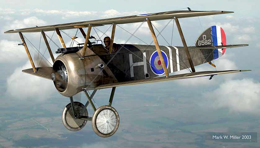
Now let’s move on to a slightly more complex thing. We need to draw the front and side windows of the cockpit. It is important to understand here that the glass is flat. This greatly simplifies the task compared to the case of curved glazing. For example, as on the P-51 D Mustang.
First, we connect the points of the front edge of the front cockpit glass and the rear points of the side glass. We insert edges using the F command, selecting the corresponding pairs of points. Then insert the missing points, according to the top view.
Now let’s look at the cockpit from above by pressing the 7 key on the digital keyboard of the computer. The top view is terrible. The picture is of very poor quality. But the principle of the matter is clear. We need to insert the missing points at the “corners” where the front and side windows meet.
To insert a point on an edge between two others, select the edge and execute the Subdivide command, which is located on the left tab of the main program window. It is called by the T key. Press the Subdivide button of the Add panel. Between the selected points, another one will appear in the middle of the edge.
Now you can see where the upper corner point of the cockpit glazing should be. The same applies to the lower corner point. We also divide the bottom edge with the Subdivide command and put the resulting point in place. We connect the corner points with an edge. Let’s see what happened.
It turned out badly because our drawing of the airplane views is very bad. The top view does not match the side view. We’ll have to use common sense and photos of the prototype. Common sense tells us an important thing from the point of view of geometry: the cockpit glass is flat, that is, all four points of each glass must lie in the same plane. Photos of the prototype show us the shape of the cockpit.
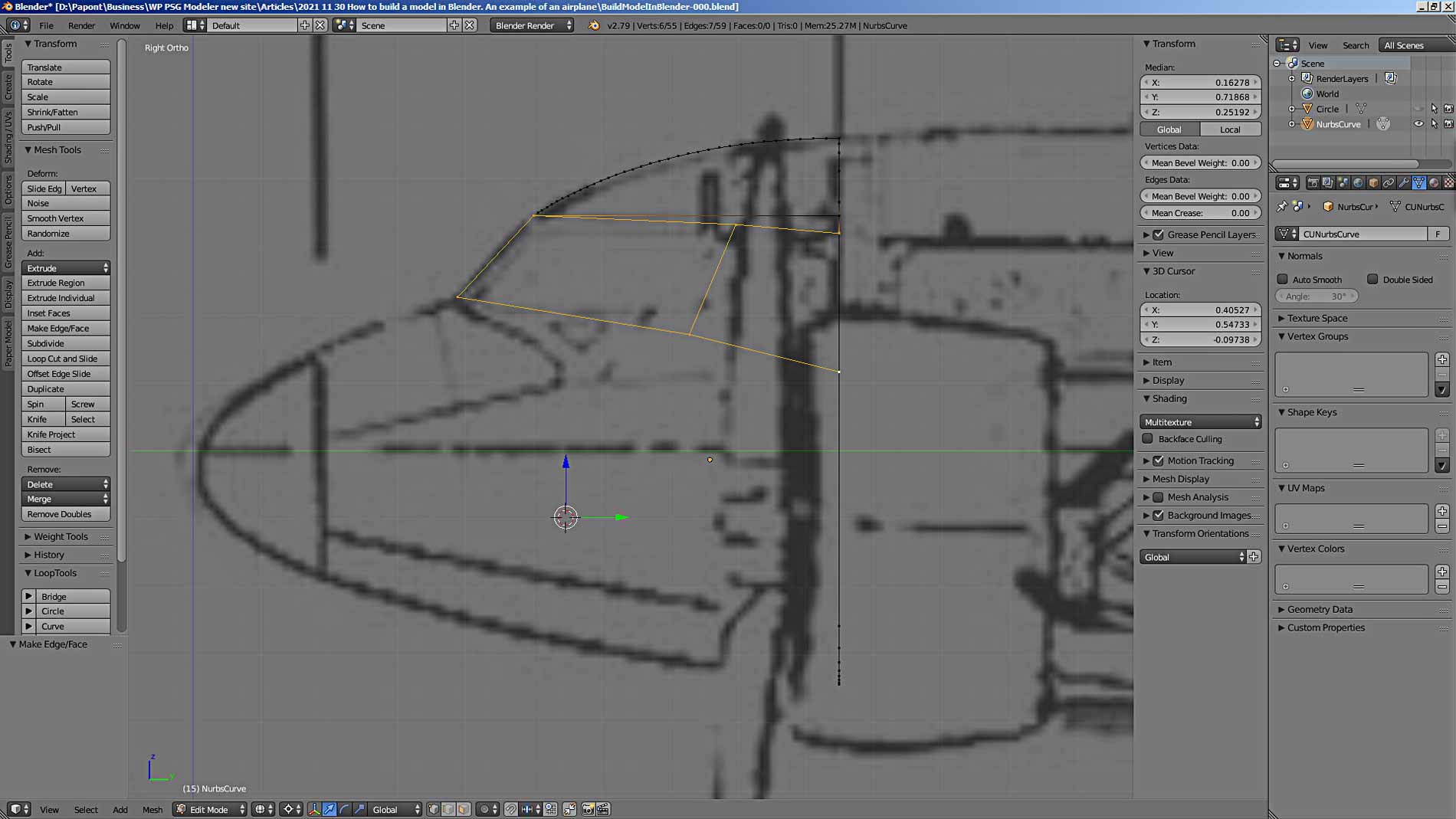
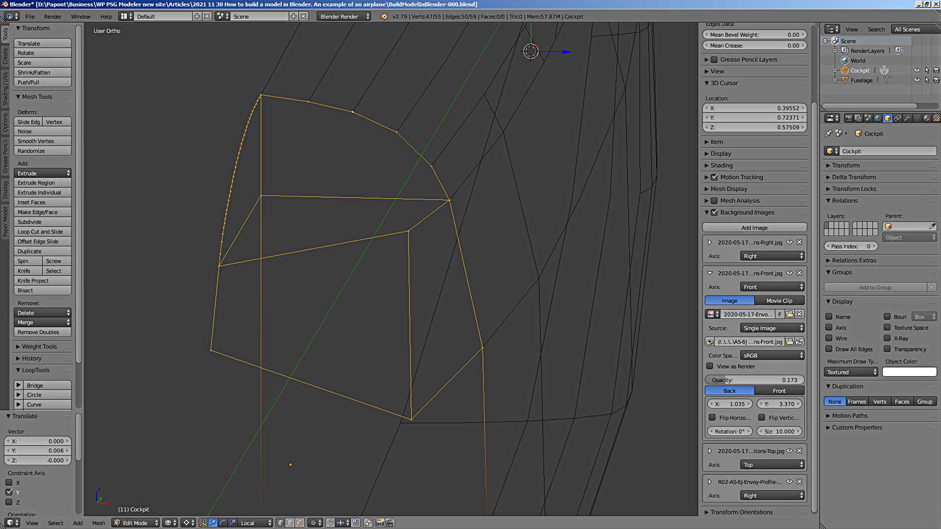
Let’s try to make a “good” cabin. Since we have taken the Side view as the main one, we will be guided by it. The upper edges of the front and side windows of the cab run horizontally. The bottom edges are tilted. Let’s draw the forward and side glasses in accordance with these conclusions.
Not bad, just fix the front top vertex of the front glass. It must be lowered onto the line connecting the fuselage roof and its lateral inclined panel with the windows. The result is an “improved” view of the cockpit glass.
In general, if you don’t like something in the shape of a contour or an object, then there are two ways to fix things. If the corrections are insignificant, then it is easier and faster to move several vertices to the “correct” places. If the fixes are large, then it is easier to redraw the object.
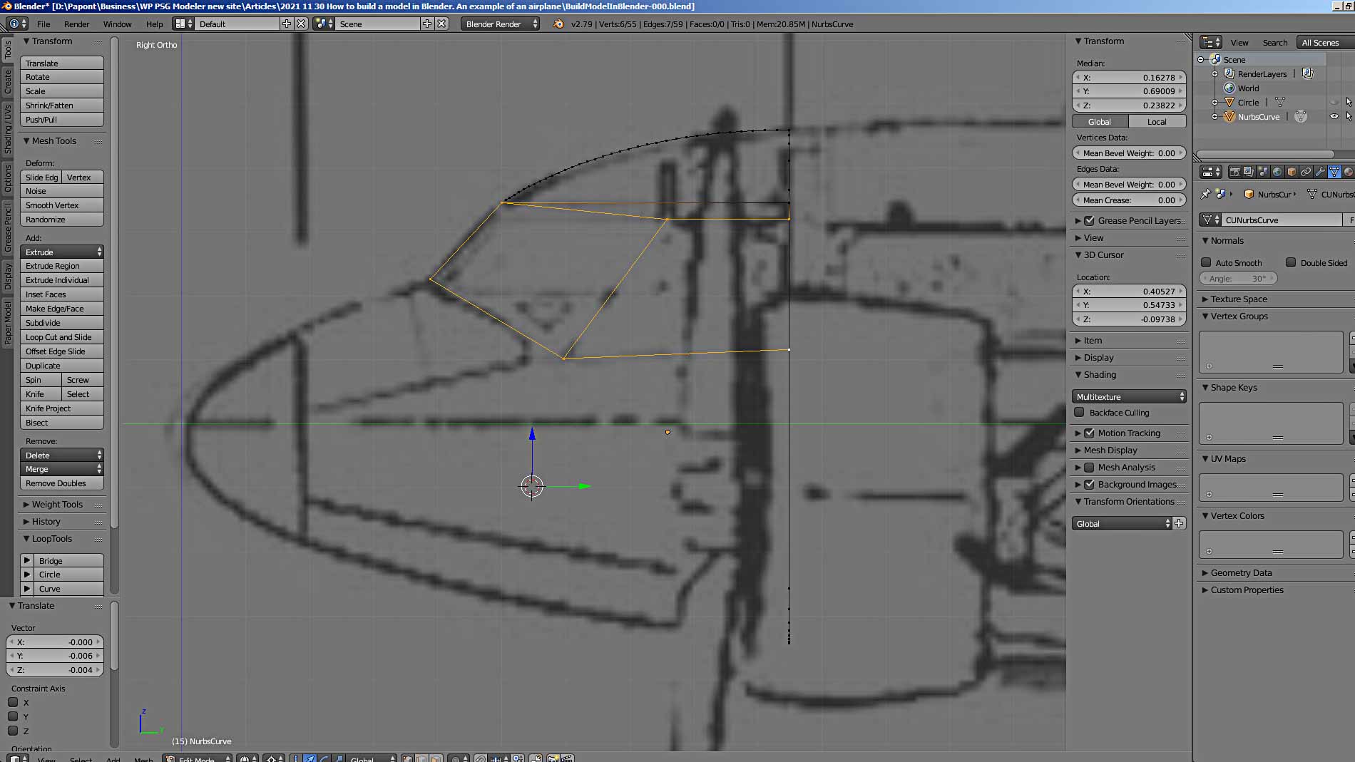
We now have a “good” side view of the cockpit. If we look at what happened in perspective, we will see that the side glass is not a smooth continuation of the side panel of the fuselage with portholes, as on the prototype.

There is a fracture in the transition from the panel to the side glass. We need to correct this situation.
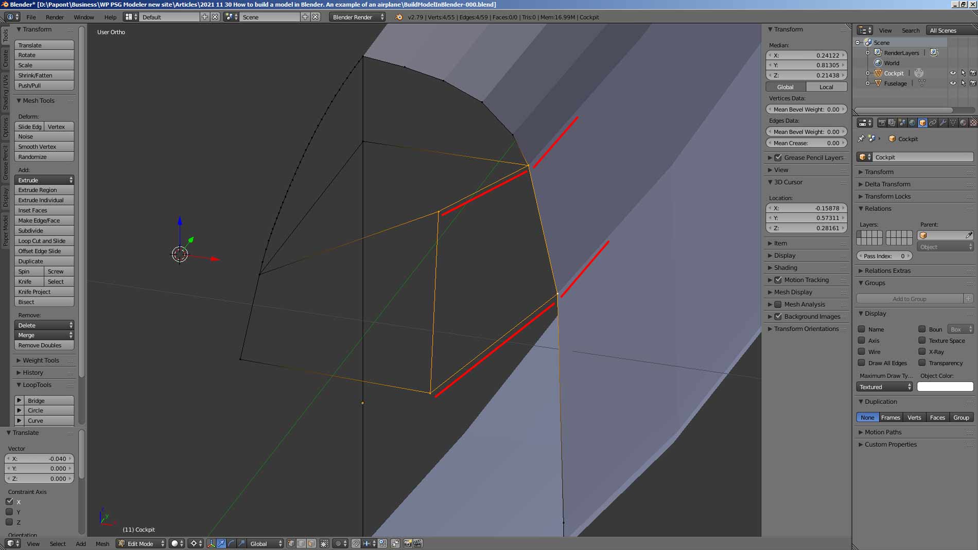
To correct the shape of the cockpit, it is necessary to move the left points of the side glass along the X-axis along the width of the fuselage, achieving a smooth transition from the side panel of the fuselage with portholes to the side glass of the cockpit. We can select at once two left points of the side glass and move them outward from the center plane of the fuselage. It is convenient to “drag” points using the coordinate axes marker. Move the points using the red arrow indicating the direction of the X-axis.
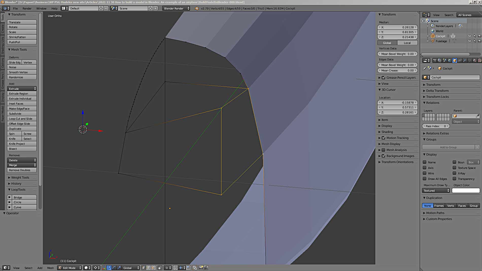
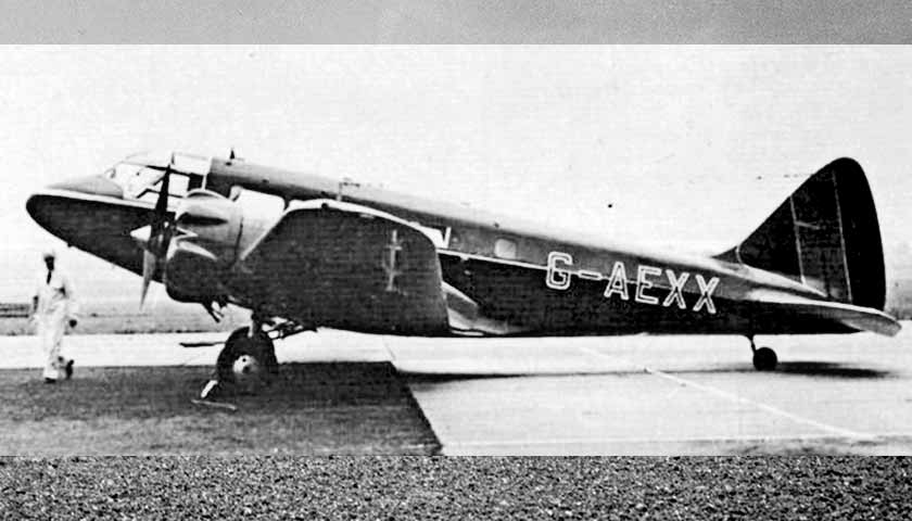
Let’s see what happened. To make sure the model is correct, you need to use photographs. The more photos of a prototype you find, the more accurately you can model it. However, the photos are taken from different angles and may not be an accurate representation of the prototype as shown in the factory drawing. This must be taken into account when modeling.
At best, photographs can show you only small fragments of a prototype without distortion. Those places that are near the optical axis of the camera that took the picture. The removed parts of the prototype will be distorted and will not be able to show you the exact shape of the object. But only the principle of its formation.
I have combined the model of cockpit glass we received with a more or less suitable photograph of the aircraft. Here’s what I got.
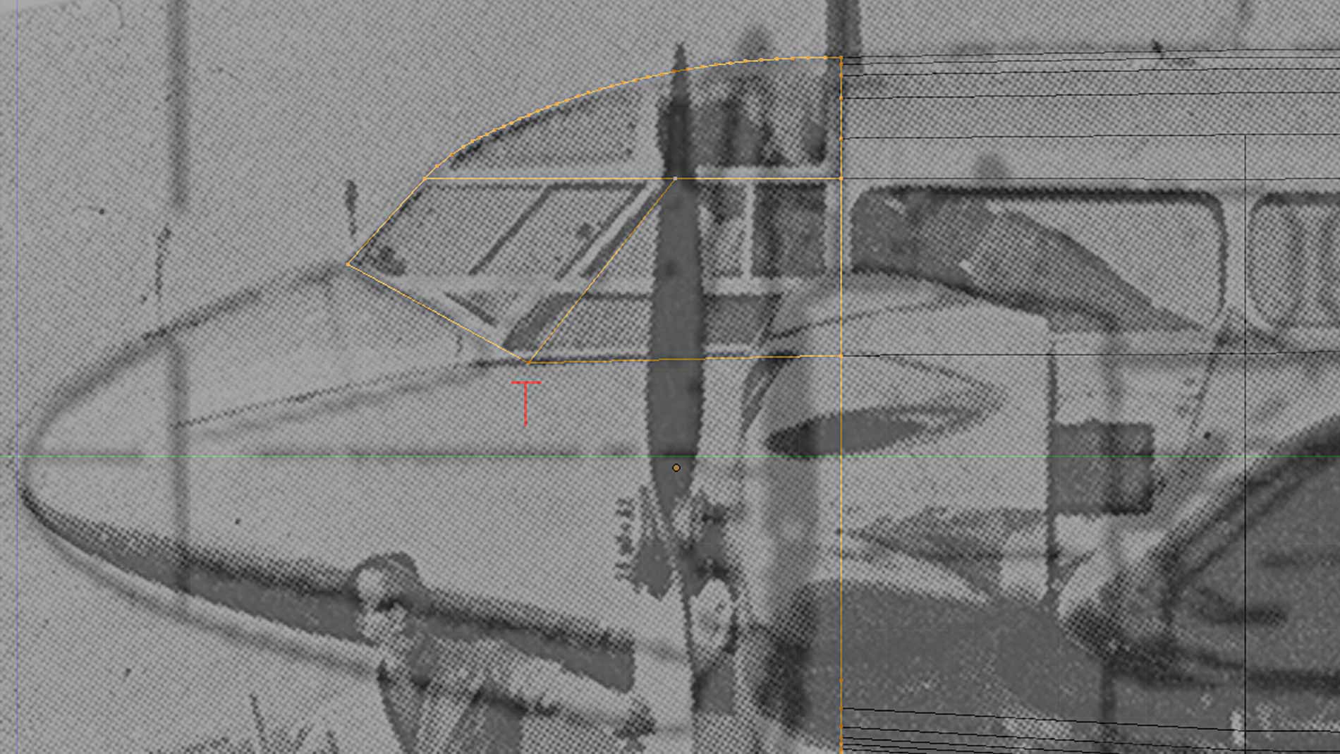
Here you can see that the upper left and lower left points of the side window can be moved slightly towards the nose of the aircraft. In general, in order to understand the spatial arrangement of parts and feature lines and points of an object, it would be nice to know the general principles of spatial construction of objects.
These issues are dealt with by a special science that I studied at the institute. This science is called “Descriptive Geometry” (See in Wiki https://en.wikipedia.org/wiki/Descriptive_geometry). It contains a number of rules on how to get the true dimensions of an object from its images. A very useful thing for 3D modeling.
Let’s make some minor edits to match the last look.
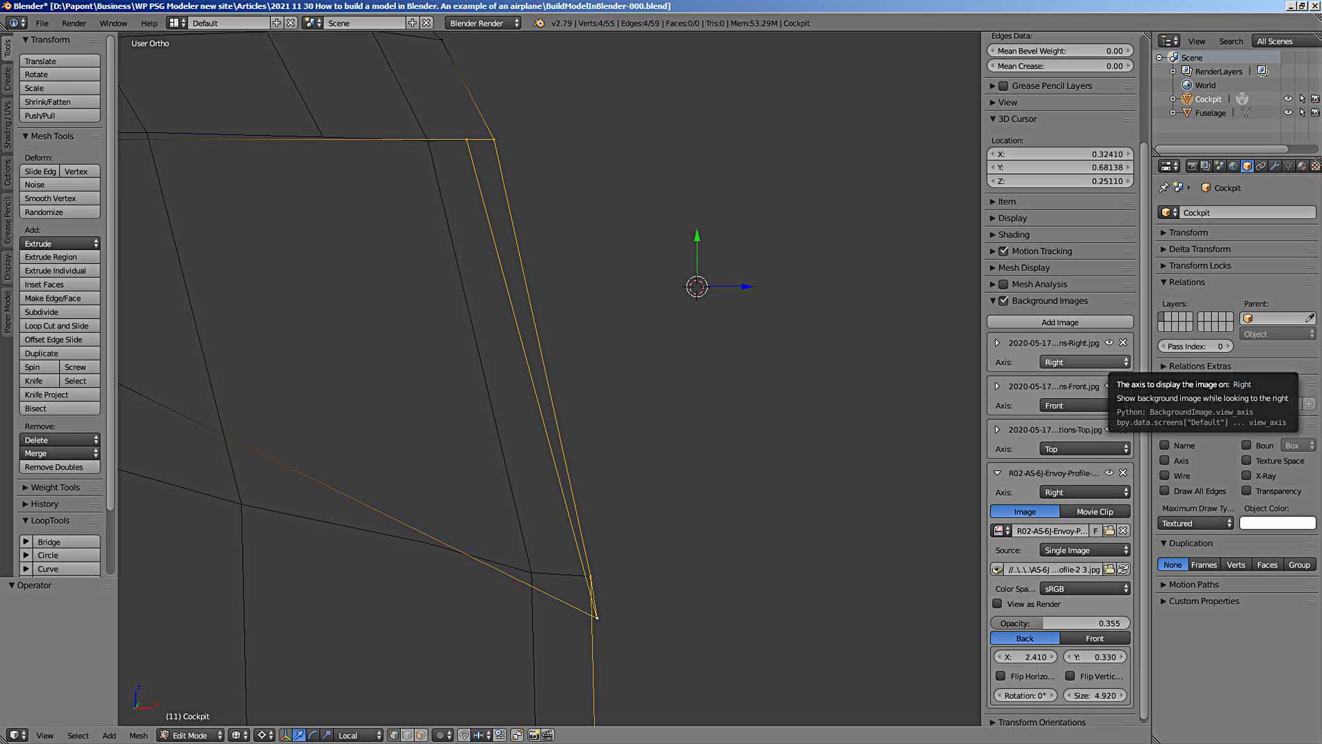
To edit with help a photo, you first need to put this photo in the field of the main program window. This is easy to do. In the right tab, which is called on the screen with the H key, there is a Background Image panel. Press the Add Image button and add the photo you need. All parameters and adjustments are very simple and there is no point in talking about them here. You can easily learn how to use them if you read from the titles.
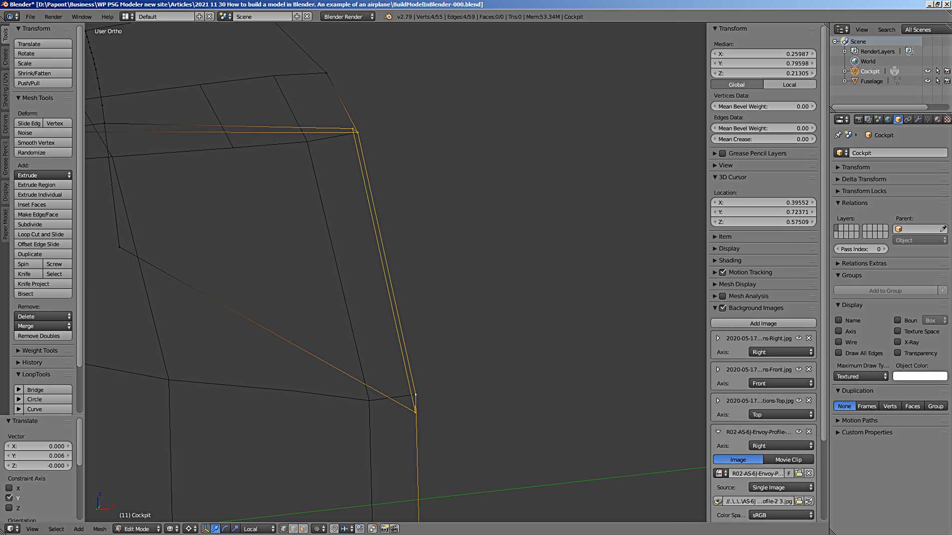
Now we need to do one more glass check. They must be flat, without distortion. Let’s look at the side glass from the end. Opposite sides should be parallel, then the glass is flat. Let’s take a look at the side glass in front.
Let’s fix the skew of the side glass.
We will do the same procedure with the front glass. As a result, we got quite similar cockpit glasses.
We will make the nose part next time. See you.
To be continue…