After some deliberation, I decided to return to my unfinished model, on which I was mastering the modeling techniques in Blender. It is not good to somehow leave the job unfinished. What is needed to model an object. First of all, information about its form. This data is given to us by a drawing: shape, parts, their relative position, dimensions. Then you can move on to modeling.
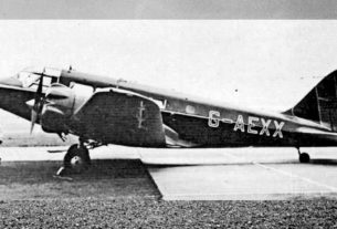
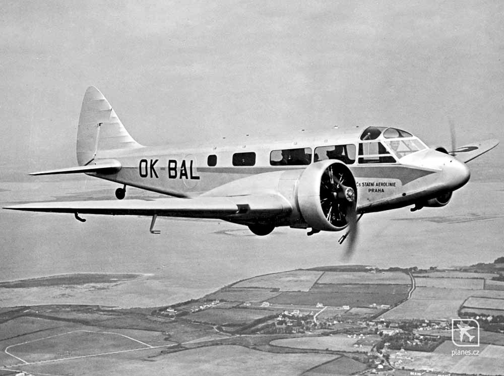
However, here it’s must first analyze your object that you are going to model. You need to figure out how to break it down to make it easier to work with. Modeling everything at once is too difficult and inconvenient. So I did. I have long wanted to make a model of an airplane in Blender. I chose a prototype for myself. It was an Airspeed AS-6 Envoy.
Some drawings of the plane were found on the net. But, there are no drawings or documents, and I decided to make from what I have. I have got such a drawing.
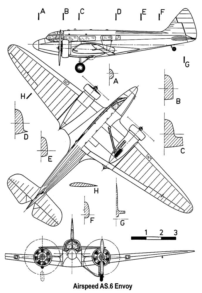
The general view of the aircraft is generally similar. With one obvious exception: the width of the fuselage is drawn clearly less than it actually is. Yes, the rings on the motors in the top view clearly do not match in size with the side view of the same rings. Well, and many more little things.
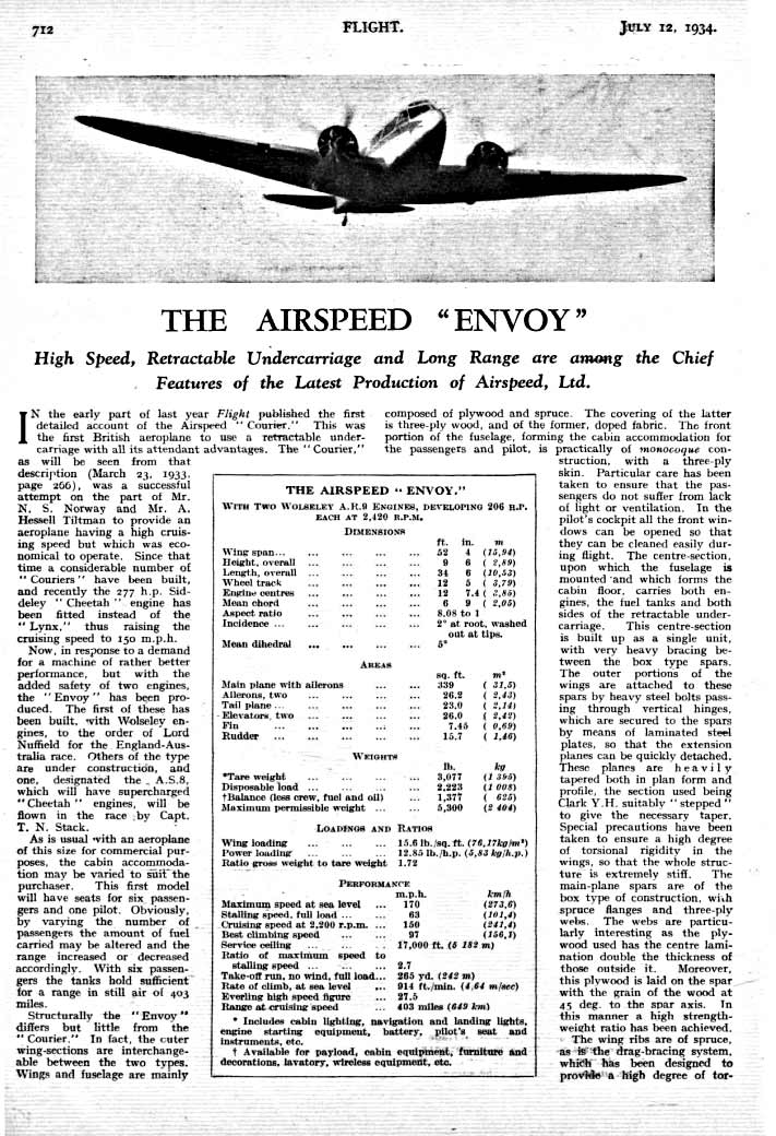
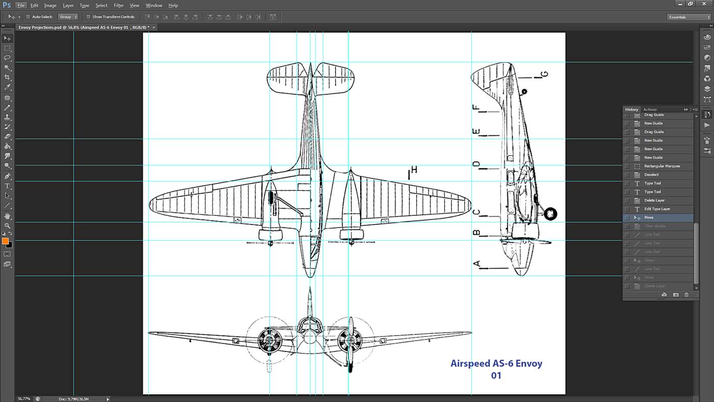
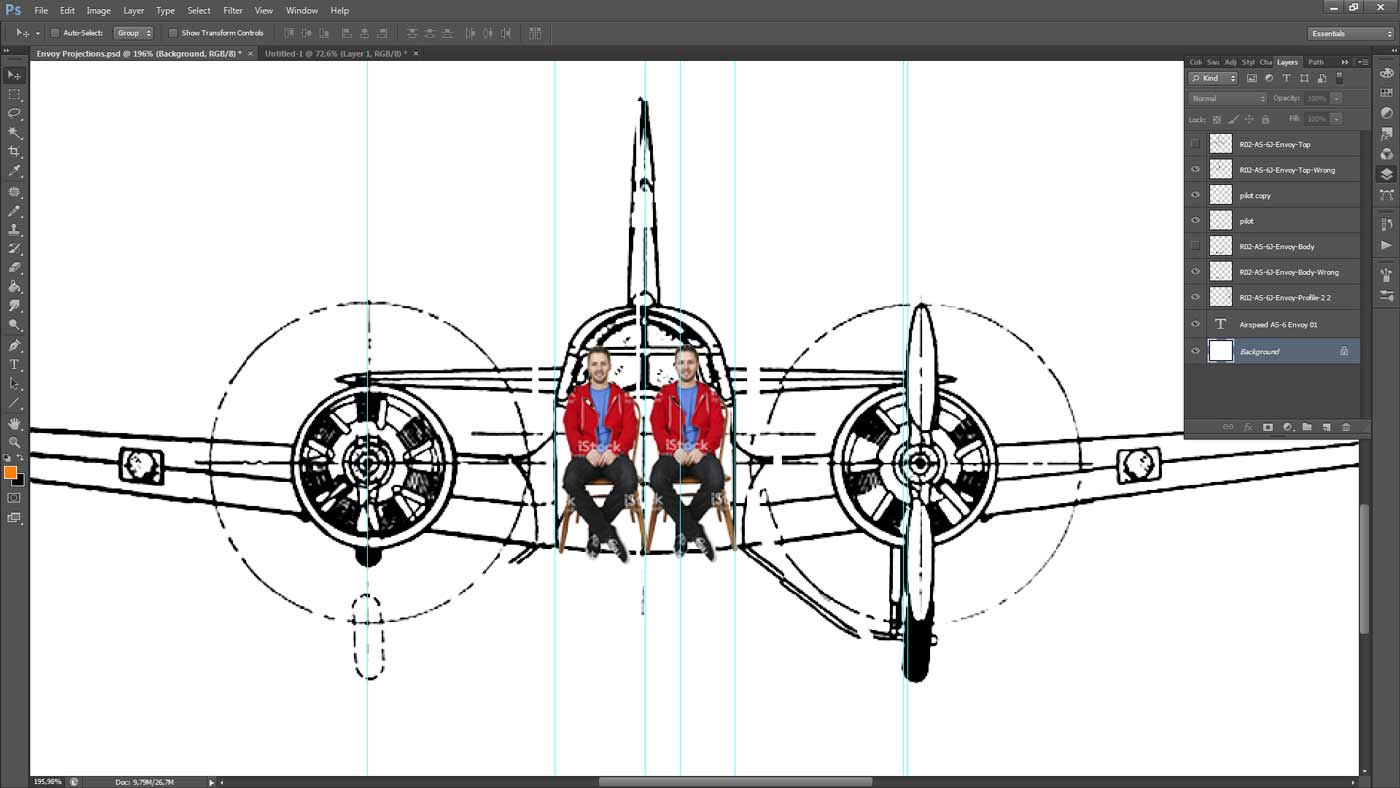
Let’s check. I found only basic data on the geometry of the aircraft. These are wingspan, length (no one knows what) and height – also no one knows what. There was also the distance between the wheels of the chassis and the centers of the motors. Then I put all this “wealth” in Photoshop and that’s what happened.
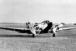
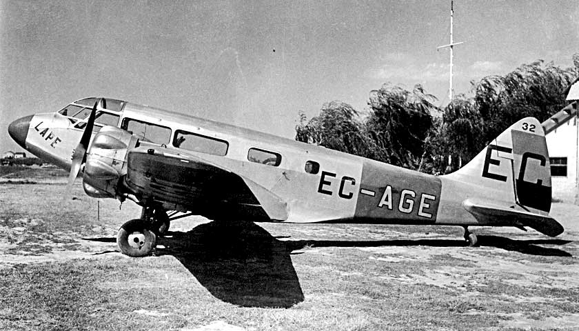
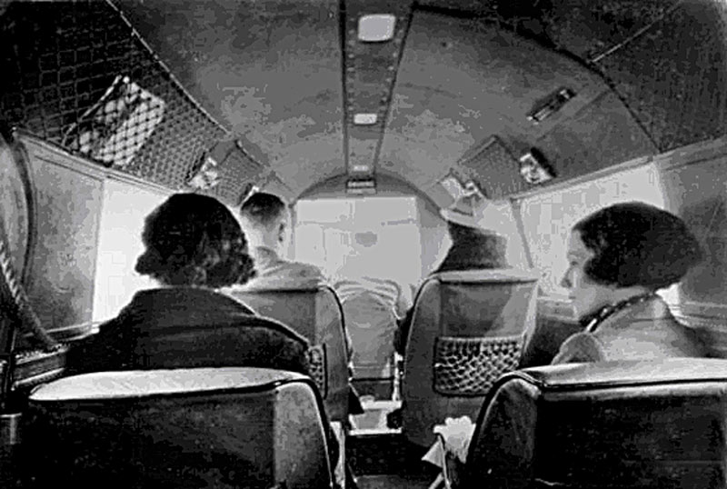
The photographs show the width of the aircraft’s passenger compartment. If we take into account that the people in the 30s of the last century were not yet as big as they became in the 70s and 80s of the same century, then we have a chair about 50-60 cm wide. Plus, the passage between them is 20-30 centimeters … We get the dimensions of the interior width of the cabin 120-150 cm. Plus the thickness of the cabin structure: 8-10 cm per side. We definitely have a total of 140-160 cm in outer width.
Let’s see what is on the “drawing”? And everything is not so there. A bunch of discrepancies and, what is most unpleasant, conflicting data. Engines should be located closer to the fuselage in terms of dimensions. And the width of the fuselage, as we just found out, is larger.
To be more convincing, I put large-scale guys in the cabin as passengers. The guy’s head is 18 cm wide, from ear to ear. I turned out to be the same!
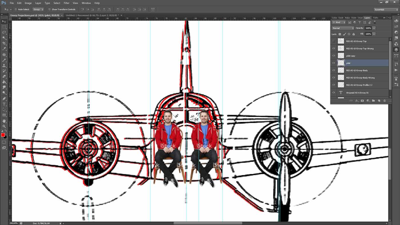
In short, the width of the fuselage had to be increased. It turned out like this.
Next, you need to pay attention to the projection lines of the drawing. Namely, the characteristic points of an object in different views must lie on the same projection lines. This is the basis of drawing (1st year of the institute). Let’s see what we have.
The fuselage length in the top view and the side view does not match. We fix it.
In the same way, you need to check the entire picture of the plane. Look at the tail, the cockpit, the location of the landing gear, ailerons, portholes, and more.
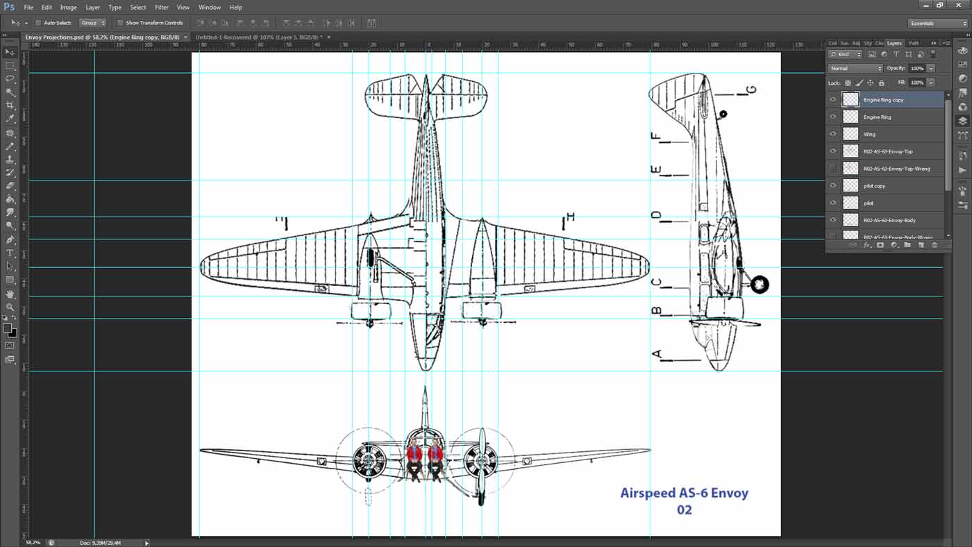
Aligning all the details along the projection lines, we get a picture of the object that is coordinated in three views. In our case this is an airplane. Well, and as far as this picture corresponds to the drawing, you can argue as much as you like.
In this case, there is no factory drawing – which means there are no arguments in one direction or another. Well, actually, what is there to wish for more? But there will be more freedom in modeling.
Choose your prototype wisely! 🙂