
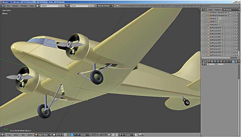
Let’s continue. It was now the turn to take the first step in 3D modeling. I hope you already know what objects in Blender are made of. Vertices, Edges, and Faces. With their help, we will create the shape we need.
First of all, I want to warn you: do not look for perfection in the created objects immediately. Here we need to understand that the objects that we create from the main Blender primitives are still a conditional representation of the object. The final look will be given only by visualization – render. He, with his unknown mathematical methods, will present us with the final image, which we have created using vertices, edges and faces. For now, let’s start.
Let me remind you of the procedure. First, we will make a theoretical fuselage framing using our picture, then we will pull it into a block, part of the fuselage. Let’s open our “blueprint”. Preliminary, we must have added images of our frames to it in the same scale as the whole picture.
The first question is: what to make a theoretical frame from. Drawing it point by point is very difficult and very long. As basic common sense suggests, the easiest way is to make our frame out of something similar. Blender has a special set of ready-made flat shapes – flat primitives. The word primitive means, in our case, an elementary geometric figure that stands out as a “building brick” for almost any object.
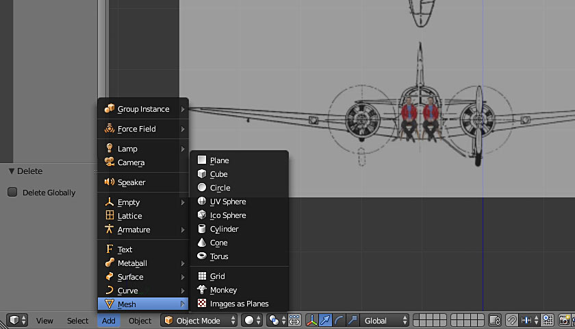
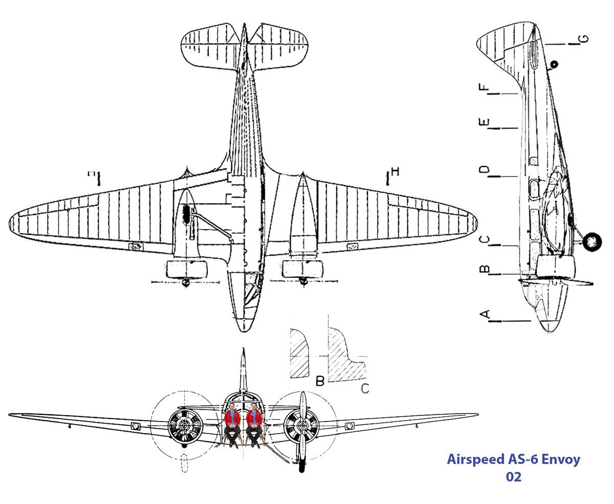
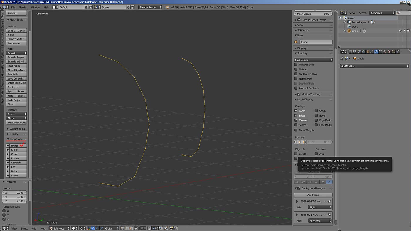
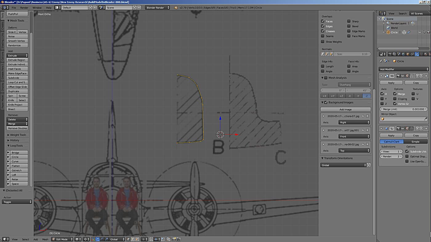
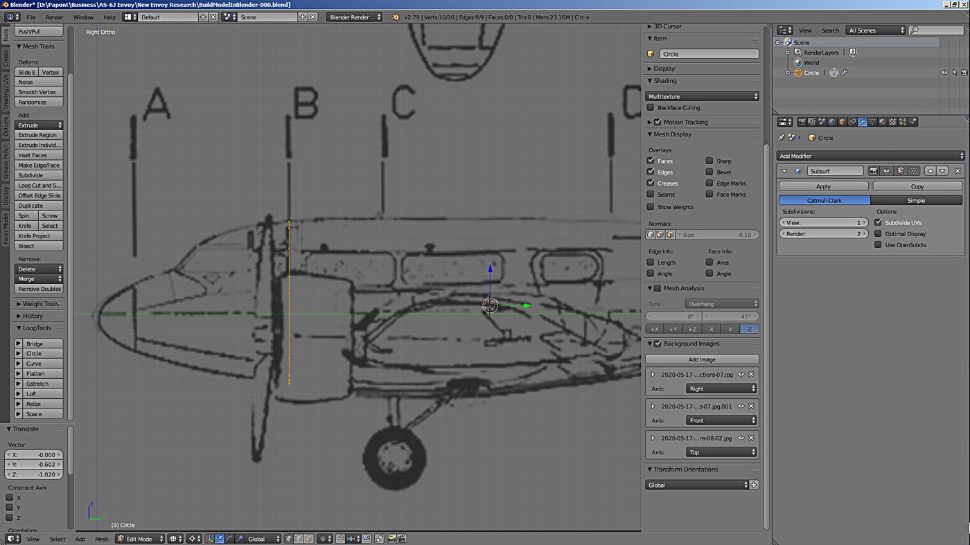
We look at our theoretical frame, take, according to the logic, frame B. It looks like an oval with a straight bottom in shape. Therefore, we must try to make the frame from the circle. Go to Blender and select the circle. It is easy to choose, but what parameters should be set for this circle? I must say right away that the default parameters do not suit us in our case.
How to be? We call on common sense to help. We analyze the shape of our frame. It can be divided into an arc that is on top, then there is an inclined straight line. Then a vertical line, then a small radius and a smooth arc.
Obviously, you only need two points to set a straight line. Here, some may regret the wasted time at school in geometry lessons. Geometry is essential here.
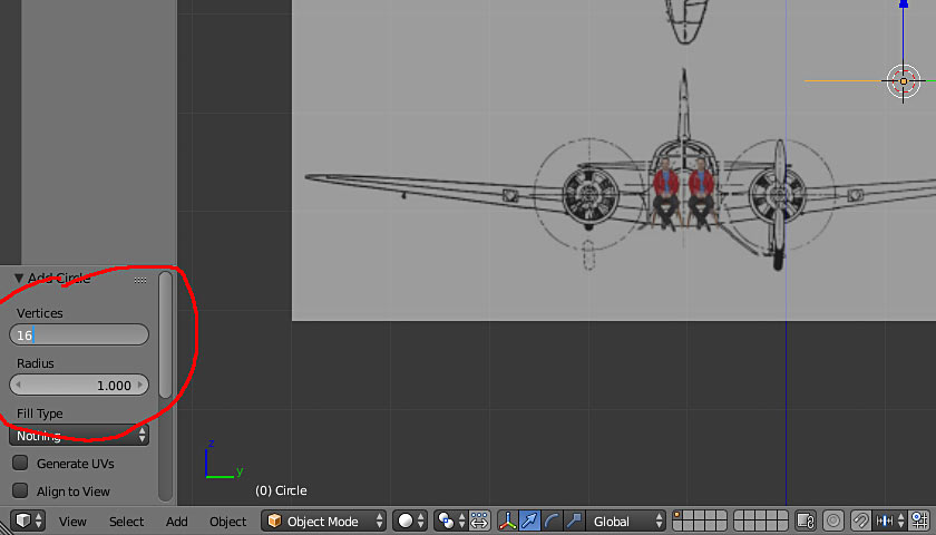
Further, we understand that arcs, elliptical segments, in general, any curve, will be constructed the more accurately, the more points we specify for its construction. Again a dead end. Yes, this moment frightens off many. And this is an objective problem: how many points to set for an object when modeling it. Ask a little – you get a crooked broken element. If you ask a lot, the computer will slow down, processing this crowd, and it will be difficult to look at such a drawing. In the eyes will ripple from so many peaks. In general, we take 16 pieces. It will not be enough – we will add. There will be a lot – we will remove it. And then we will extend a suitable number of vertices to all other frames.
That is why, in order to reduce the number of points in modeling, special tools have been invented in Blender that help to easily and gracefully solve this and other similar problems. These tools are called modifiers. That is, by applying the modifier, you get your curve already in the desired representation, which is created on the basis of a mathematical algorithm. And all the details unnecessary for modeling are omitted.
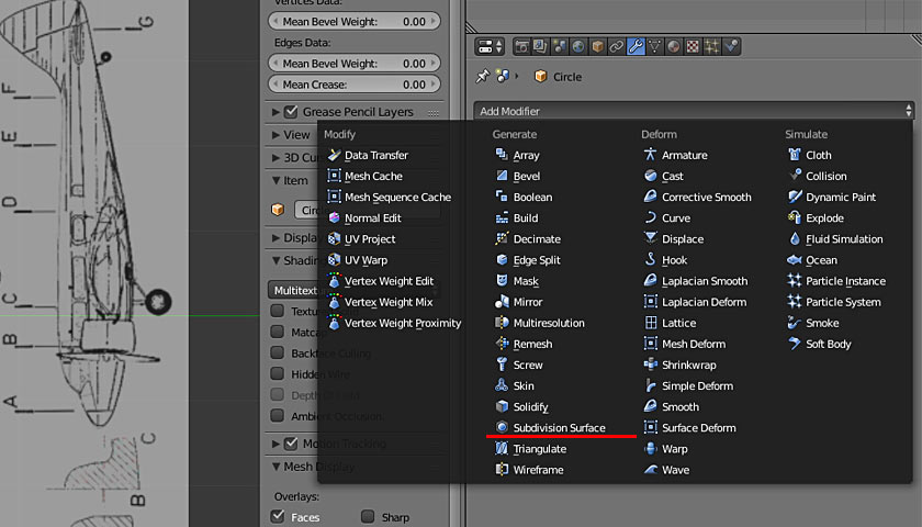
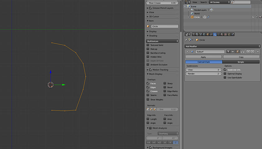
The main tool for bending curves and other objects is the SubSurf modifier. It works like this.
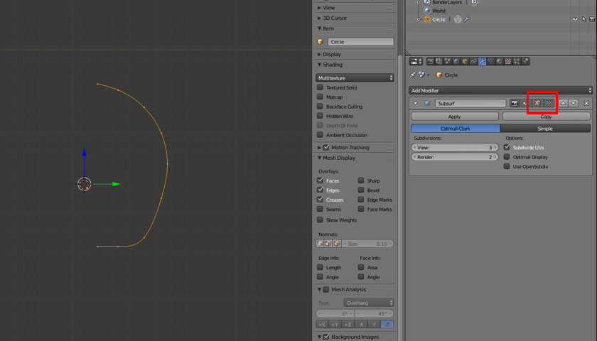
For surfaces, that is, for meshes, the modifier works like this:

Please note that the modifier settings are very sensitive and must be used accurately. Therefore, as with other Blender tools, you need to experiment with this on some simple object and understand what affects what and how. But it is better to write down the results of your research in a special notebook. So that a huge amount of information from Blender is not lost, flying out of my head.
Another important point that the Blender developers have foreseen: the modifier can be omitted! You may even not use it at all. What does it mean? This means that working with the modifier consists of two stages. First: you call the modifier from the section with modifiers and it appears on your desktop. Next, you customize it as you need. In this case, you immediately see the result of the effect of the modifier on your object.
BUT! The most interesting thing is that although the modifier is in effect, it has NOT been applied to the model yet. And it can always be canceled or rearranged in the modifier stack to another place. Because the order in which the modifiers in the modifier stack are, stacked has an impact on the end result of your simulation.
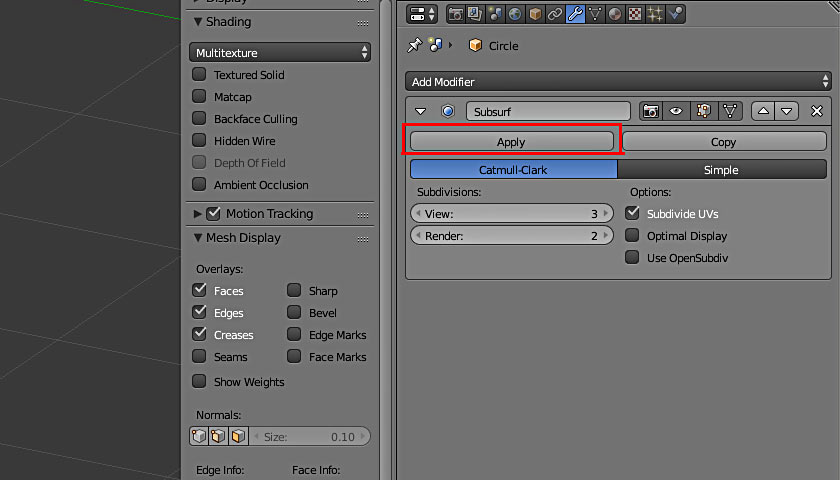
We look at the modifier panel. Its effect can be represented in two different ways. Choose which one is more convenient for you. I have already shown this in the pictures above.
Now, knowing that we can do with fewer vertices when modeling, we again return to the question of the number of points needed to model a given frame. This question will arise when modeling any new object. Look and try. The general principle is as follows: in order to obtain a “correct” model, the number of points in all frames at the first stage of modeling must be the same.
This is from the area of topology, this is mathematics. However, we can use the results from this case as a kitchen recipe…
So, topology examines continuity, including meshes, as elements of space. Our mesh, the mesh that will describe our model, should turn out to be continuous, without breaks, not “over tightened” or “wrinkled”. These are all mathematical characteristics, which at the output will give us a beautiful mesh that will unfold well on a plane and will only delight us.
It should be noted here that the faces that Blender operates on are mostly quadrangular. Although the program then breaks them out into triangular ones. So – four points, as we know from geometry, may lie no in the same plane. Therefore, a quadrangular face can be non-planar, that is, a face can be three-dimensional.
This is one of the reasons that when using the Paper Model plugin to unfold your creation, this “villain” refuses you in unfolding. This is a sign that your mesh, relatively speaking, is “wrinkled”, is not made according to the rules of topology and cannot lie on a flat.
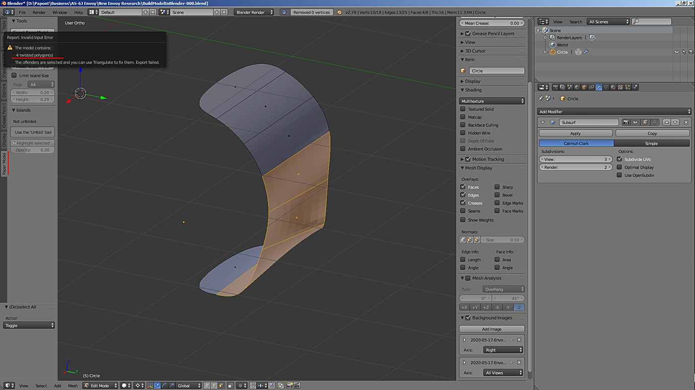
The most interesting thing is that Blender has tools to check the grid on flatness. This is for the very moment, when you do not understand why your mesh doesn’t want unfolding. Which often happens. See the picture above.
Many tools in Blender are built on topology principles. And a very important one is the Bridge tool from the LoopTools suite. It allows you to connect two different objects together with the right mesh.
And this can be used as an option along with the Extrude tool when creating any objects where this tool can be applied.
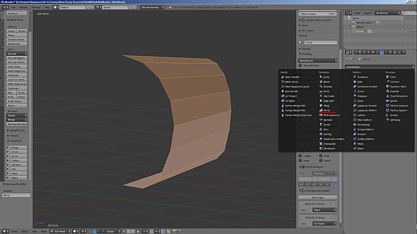
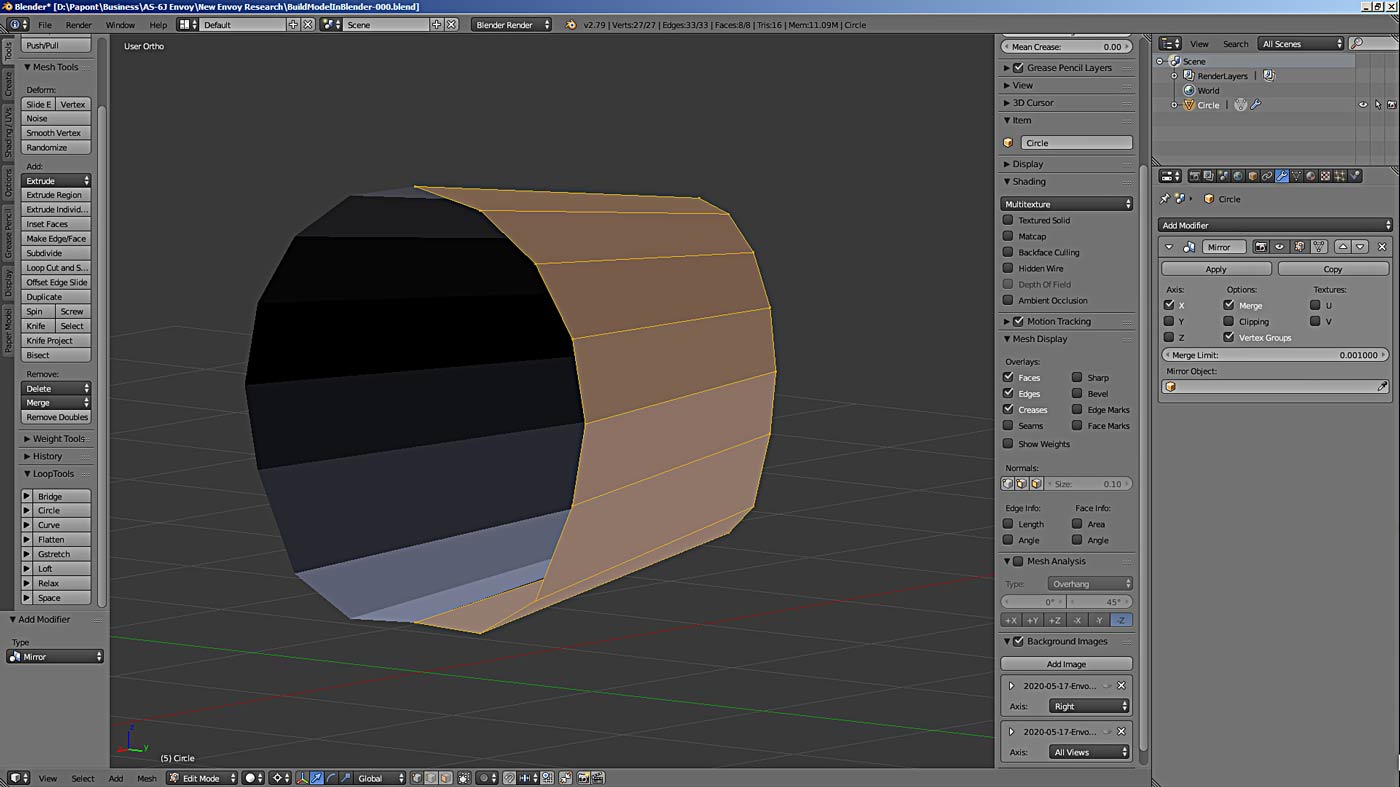
Another and last tool for today that makes life a lot easier for the modeler is the Mirror modifier. It allows you to build symmetrical objects. That in the case of our plane will be a real salvation. Exactly half of the volume of work with the fuselage will be done by this wonderful tool.
You should consider it in some simple form. Do experiments. Write the results in a notebook. This will help you to be more productive in the future and not waste time looking for sane guidelines.
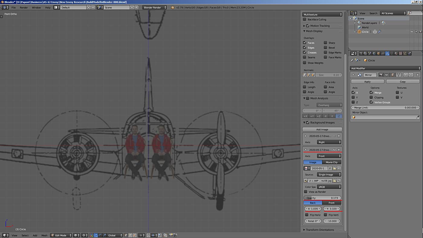
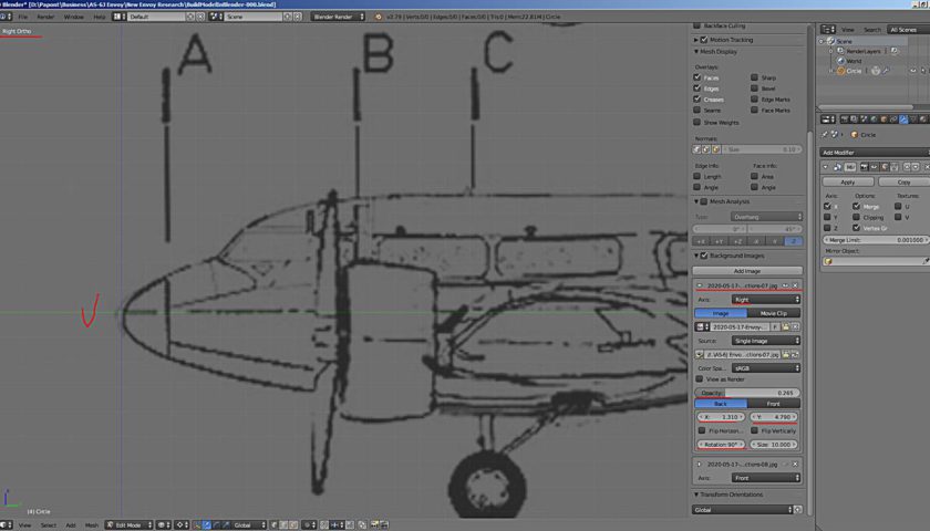
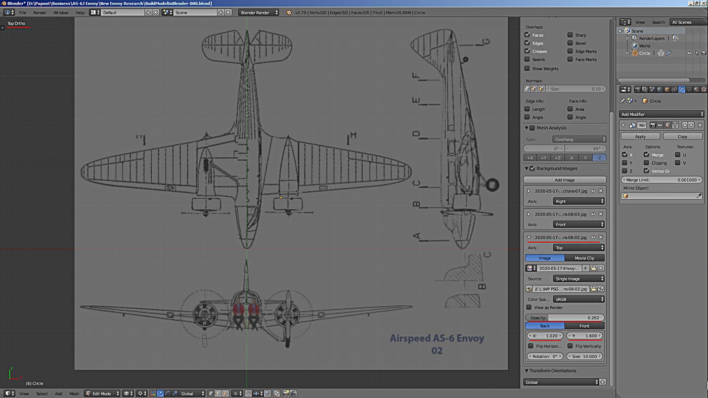
I did not mention one important point. About our “blueprint”. For now, our “blueprint” just lies in the area of the program’s modeling, in the 3D window. So, for each type you need its own separate picture. Therefore, you need to make two more copies of such a picture, and substitute them in the corresponding views of the program window: front view, side view and top view. For the convenience of modeling, the building axes of the aircraft in the views of the picture must be combined with the axes of the 3D modeling space. It should turn out like this.
Okay, now our frame is ready.
It should be noted here that the Subdivision Surface modifier (this is its full name) has a “quarrelsome” character. It deforms the object as we need it, but at the same time it “strains” it very much. This condition can be compared to a highly stretched rubber band for a vertices’ contour, or a tightly stretched rubber membrane for edges. Any interference with the resulting structure can lead to undesirable and unpredictable results. There are all sorts of methods to deal with this case. But, about them later. Otherwise, we will drown in information.
Who wants to experiment with this modifier and its work consequences, I can suggest such moves for now. Take a look at the Bevel tool. With its help, sharp edges are made between the “rubber” edges. The Crease tool has the same effect. It creates a sharp edge at the border of the “rubber” edges. Well, and so on. All of these things are covered in the Blender Guide.
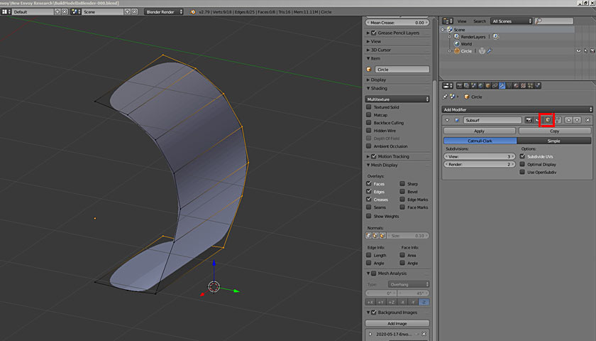
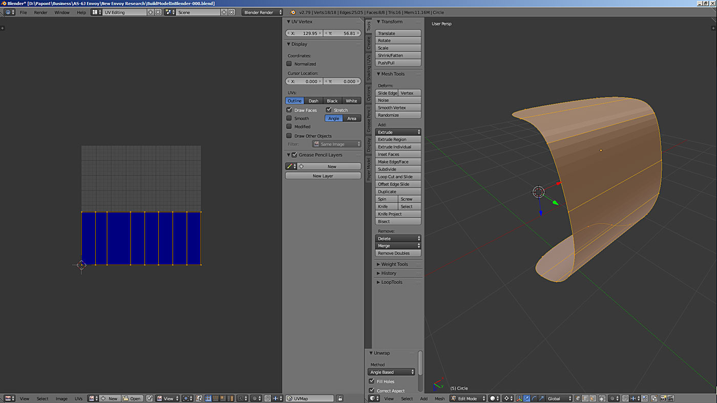
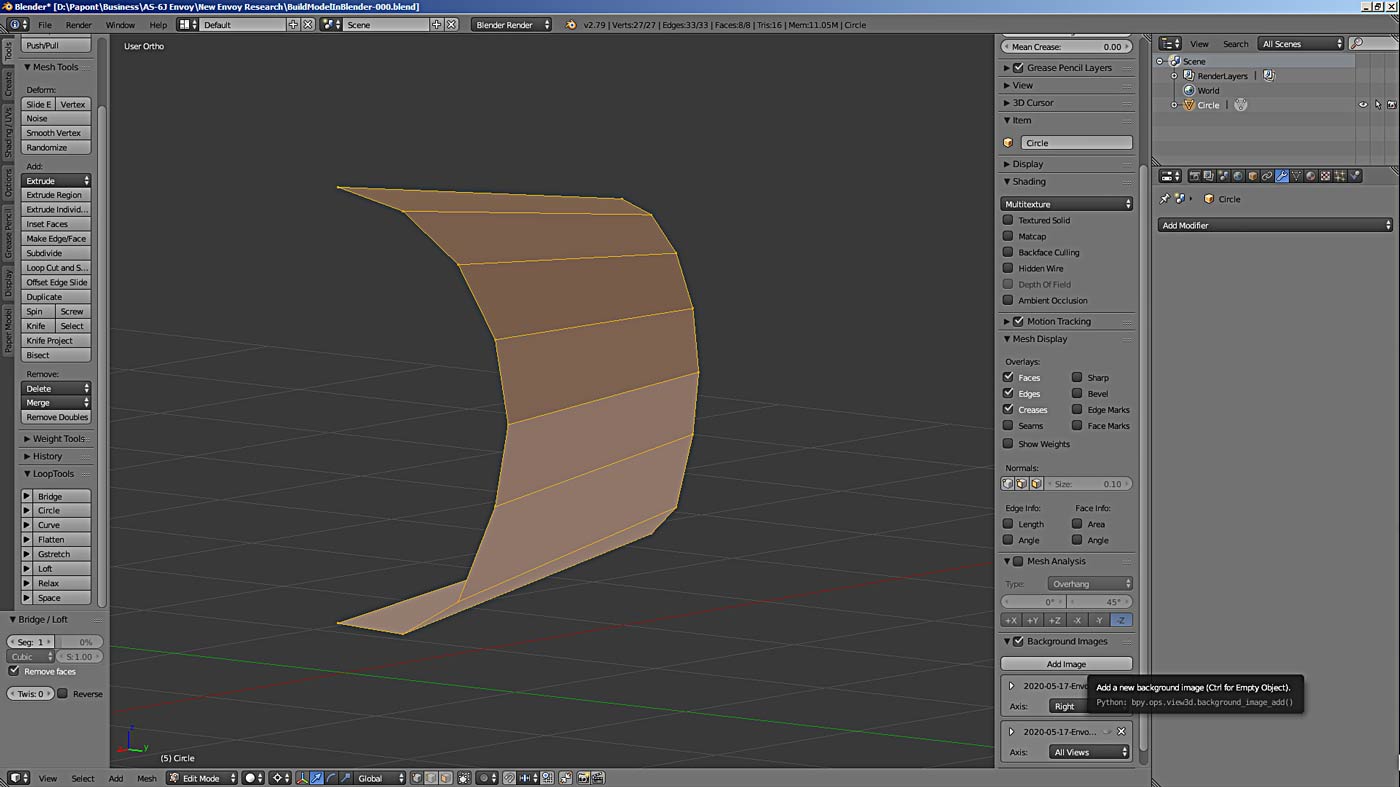
Now go to the side view and apply the Extrude tool. We have to extrude our frame to the next one C. We get a cylindrical surface, the generatrixes of which will be straight lines. This will already be the grid. With edges. You can verify this by pressing the Z key on the keyboard. It switches the views of the model in the Blender simulation window. The button in the bottom menu does the same, see the bottom picture.
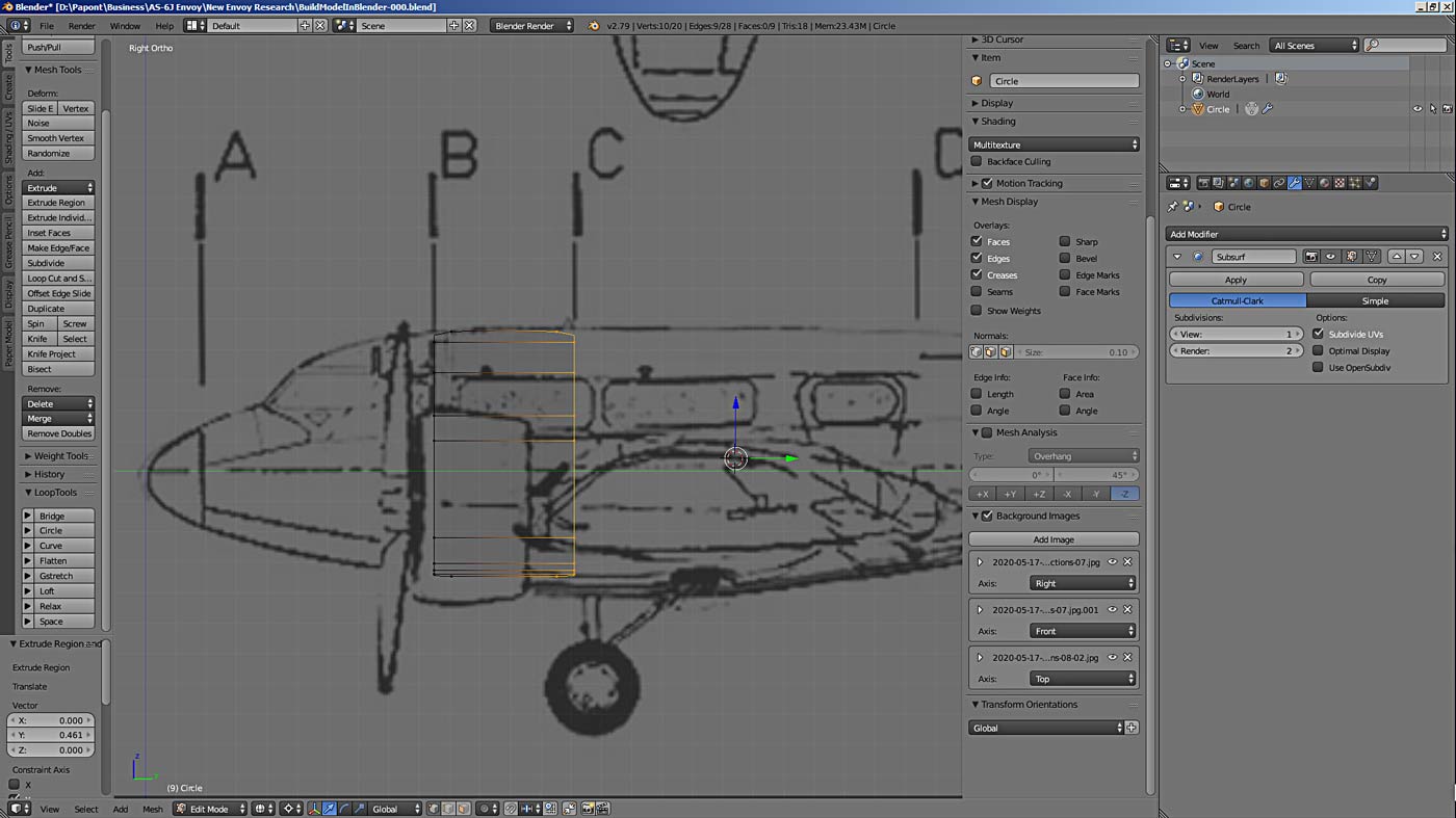
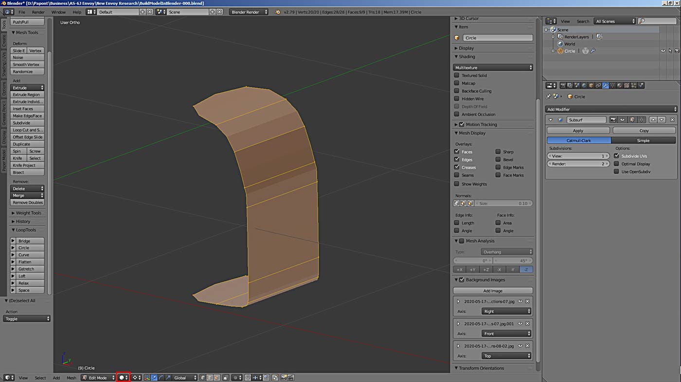
, which is reflected in its rounded edges. These are Blender problems. To correct them in this case, the Crease tool is used (the N tools tab on the right side of the modeling field). The grid view button is marked with a red square, see for yourself
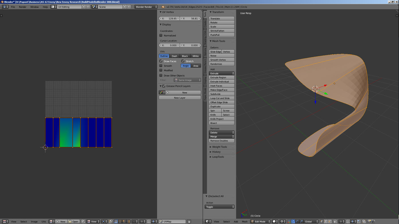
Now our task is to change the second end of our mesh and bring it to the shape of frame C. This can be done by scaling it. As we know, in Blender you can scale objects as a whole, or you can scale them separately, along the necessary axes. If it is necessary to correct the height of the object, we scale it along the Z axis. If in width, then relative to the X axis. And so on. Let’s do this scaling and get the shape of frame C on the other side of our mesh.
I think you can do it yourself just like we did frame B. Let this be your homework.