Here I will talk about how I made the first simple version of the airplane. It was 2015.
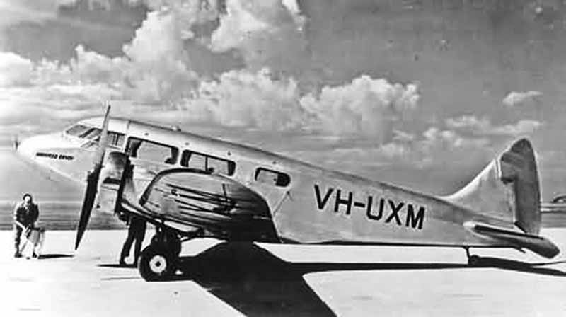
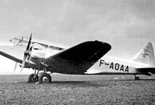
At that time, I still had quite a lot of difficulties working with Blender. I didn’t know how to model many of the details of an airplane yet. I had no drawings. There were only a few pictures and photos from the Internet.

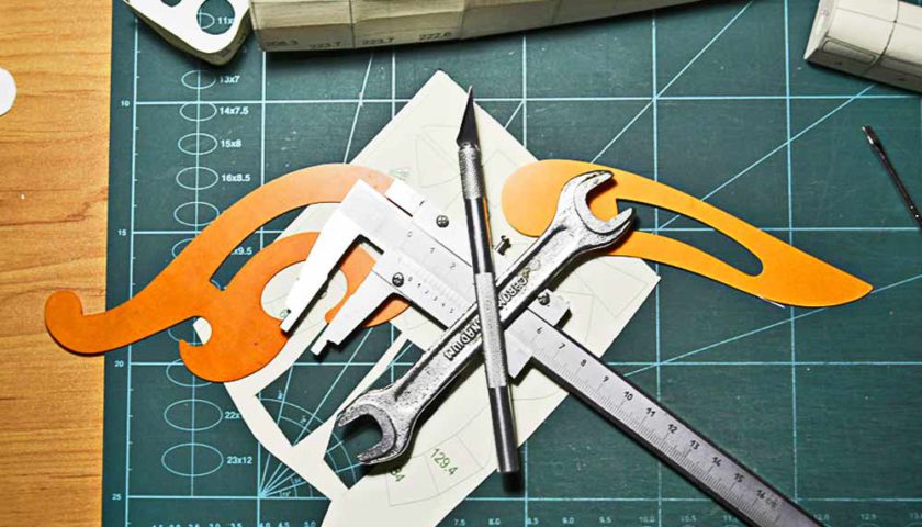
While I was sitting at the table and pondering about the future design, such a puzzle formed by itself.
Fuselage and tail unit
I began to build the fuselage using the usual technology – by kegs, which is still used today. I don’t like this way because it strongly distorts the shape of the plane. I would like to be closer to the original design.
Blender, unfortunately, is not a technical program like ACAD. It is good to model fantasy objects in it. However, modeling technical objects with given dimensions is a rather difficult task.
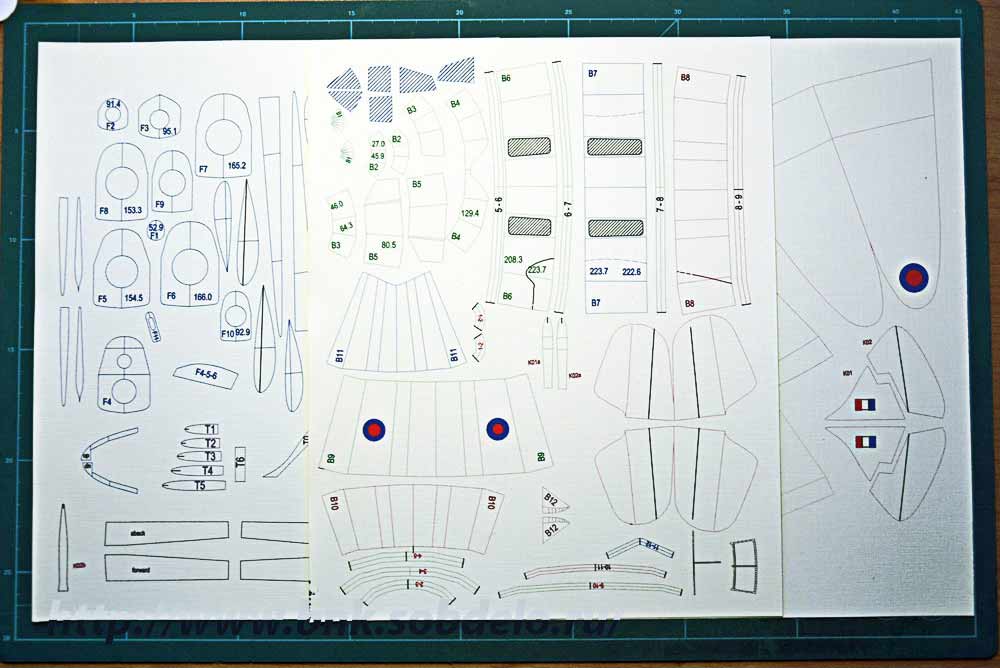
Gradually, I began to understand the basics of modeling in Blender, and most importantly, I managed to find a solution to output from Blender the sweeps of aircraft parts and bring them to the same scale.
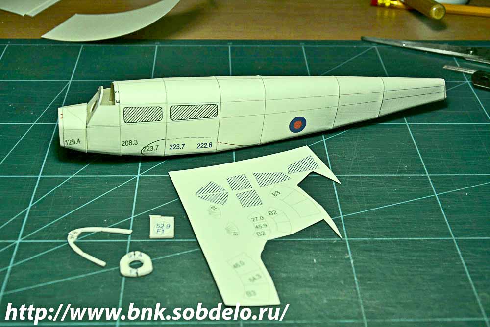
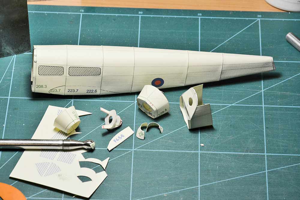
The original design of the aircraft at a scale of 1:33 had to be put aside. The paper I was going to use to build the model is too thin for a model of this size. Therefore, despite the complexity, I decided to reduce the model and make it at a scale of 1:48. My thin paper is better for this size model. Here are the first fuselage parts assembled.
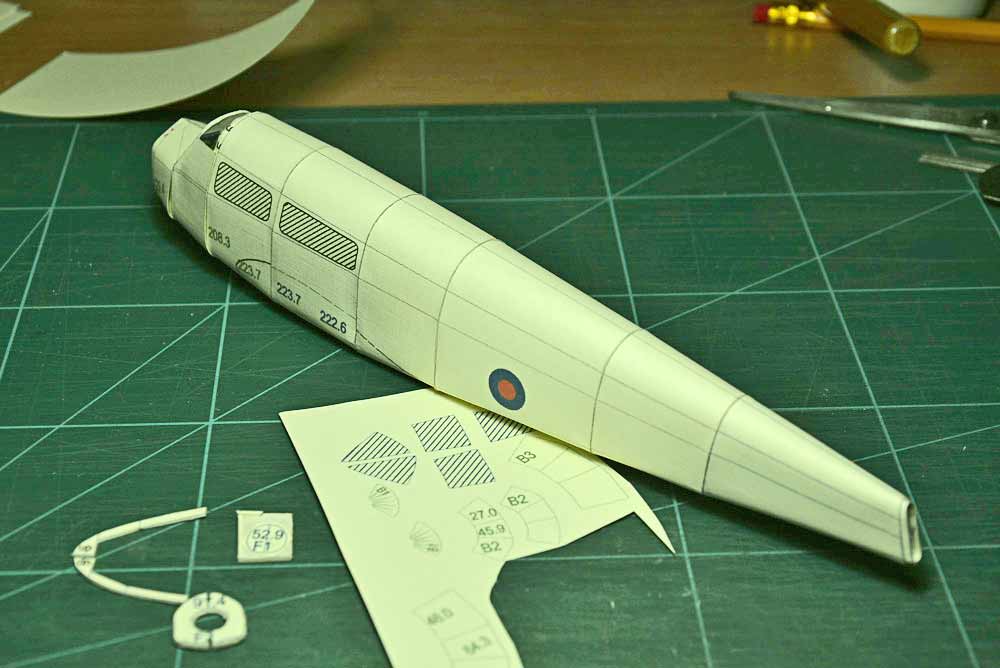
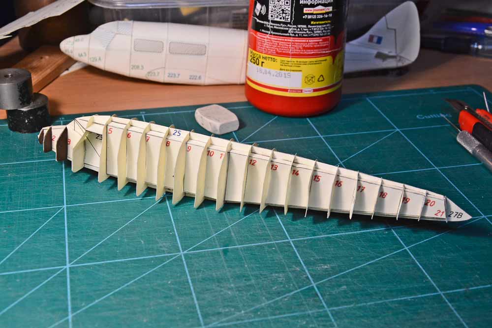
So I started designing and building a 1:48 scale aircraft in the simplest way possible. The first problem I encountered was the broken silhouette of a regular paper model. To improve the silhouette of the model, the number of kegs in the fuselage is increased.
However, this method has two disadvantages. The first drawback is the inability to completely smooth out the fuselage contour line. The second drawback is the large number of joints. They spoil the appearance of the model.
There are two ways to solve this problem. The first is to make the fuselage kegs from two halves and arrange the joints of the kegs at the top and bottom. In this way, the contour of the fuselage in the side view can be smoothed. Usually they look at the model from the side. The second way is to come up with a method to make the joints subtle in the scale of the model.
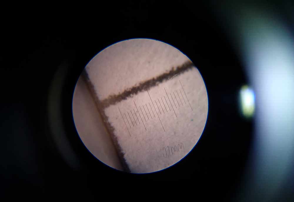
This is a separate problem and if it is solved, then the general appearance of the model can be significantly improved only by this. If you look at real aircraft, you will notice that there are joints on the fuselage too. However, they are minimal. And on a scale of 1:48, they should be about 0.1-0.2 mm wide. I was able to investigate this question after I got a microscope. Very interesting things were revealed there. I will talk about these studies in another time.
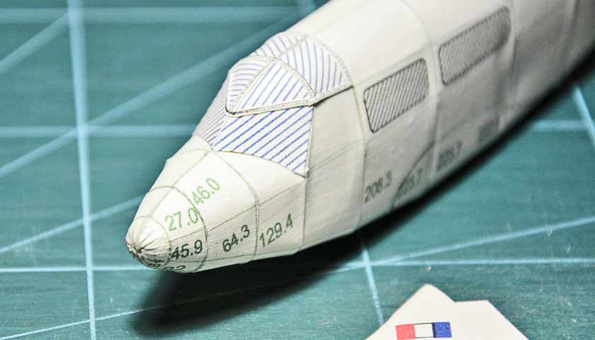
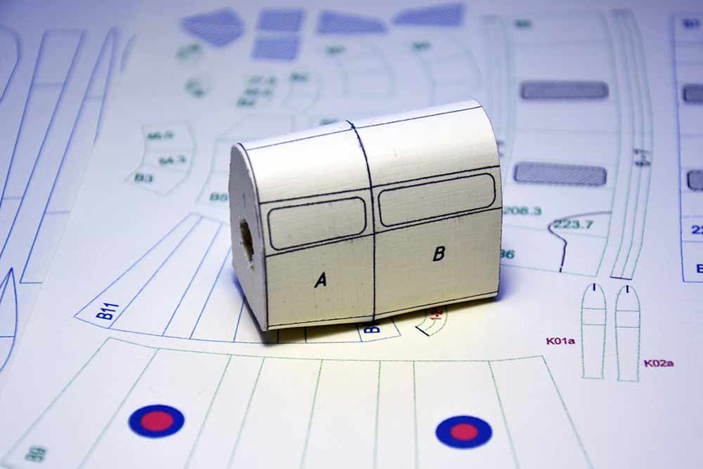
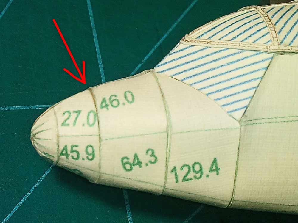
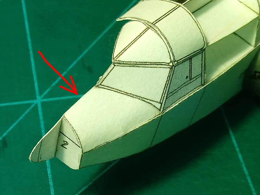
I tried to glue the nose section of the fuselage in a new way from two halves. In general, I became convinced of the correctness of this method. Until I did it well. But, I think it will still work out. It immediately became clear that for this assembly method, it was necessary to develop an appropriate frame to support the fuselage skin.
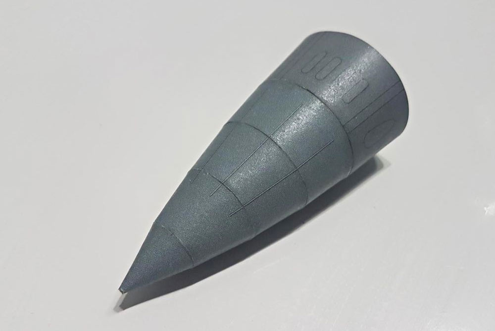
Another problem is how to make the extreme nose of the fuselage skin. Usually the nose of the fuselage is made either with a cone (bad decision) or with petals. But the latter method again requires precise scale joints of the parts. Otherwise, this design looks bad. Again, everything rests on the problem of technology of developing the joints of the fuselage skin sheets, which must be done on a scale.
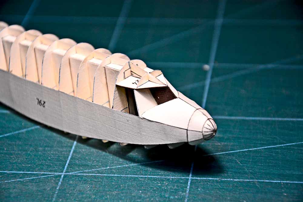
As a result of this work, the fuselage was assembled. The build quality was unsatisfactory. However, the idea of assembling in this way turned out to be correct. The fuselage contour in the nose is smooth.
The skin looked bad, since it had rather large surfaces without reinforcement from the inside with a frame. It became clear that for such a thin paper as mine, it was necessary to come up with a frame support of the appropriate shape. Then the skin will be better reinforced and will keep the shape of the fuselage better. I again came to the idea that I needed to design the plane as close to the original as possible. Then the realism of the model will improve markedly.
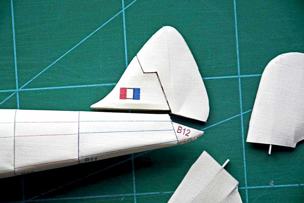
In the meantime, I continued assembling the fuselage using the old method. When I got to the rudder, I realized that it, like the vertical stabilizer, needs its own frame support. On the prototype of my model, these elements had a canvas sheathing and the frames were clearly visible underneath.
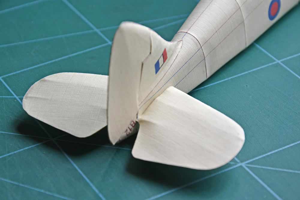
The horizontal stabilizers and rudders should be done in the same way.
To be continue….